Portable Sealant Dispense System

Active Publication Date: 2011-02-03
LOCKHEED MARTIN CORP
View PDF2 Cites 28 Cited by
  • Summary
  • Abstract
  • Description
  • Claims
  • Application Information

AI Technical Summary

Benefits of technology

A system and method for dispensing a sealant over aircraft fasteners secured to a surface in the aircraft. The system includes a nozzle tip having a shroud configured for placement over the fasteners. Sealant is metered to the shroud via an orifice within the nozzl

Problems solved by technology

Riveting pierces the sheets being fastened thus creating a potential fluid leakage path along the rivet.
These methods are also time consuming and often lead to an excess amount of sealant a

Method used


Image

  • Portable Sealant Dispense System
  • Portable Sealant Dispense System
  • Portable Sealant Dispense System

Examples


Example

It will be understood the improvement described herein is not limited to the embodiments provided. On the contrary, the present disclosure is intended to cover all alternatives, modifications, and equivalents, as may be included within the spirit and scope of the improvement as defined by the appended claims.

DETAILED DESCRIPTION OF INVENTION

The improvement(s) of the present disclosure will now be described more fully hereinafter with reference to the accompanying drawings in which disclosed embodiments are shown. The disclosed improvement(s) may, however, be embodied in many different forms and should not be construed as limited to the illustrated embodiments set forth herein; rather, these embodiments are provided so that this disclosure will be through and complete, and will fully convey the scope of the disclosure to those skilled in the art. Like numbers refer to like elements throughout.

It is to be understood that the improvement(s) described herein is not limited to the exact ...


PUM

PropertyMeasurementUnit
Flow rateaaaaaaaaaa
Sizeaaaaaaaaaa
Volumeaaaaaaaaaa

Abstract

A system and method for dispensing a sealant over aircraft fasteners secured to a surface in the aircraft. The system includes a nozzle tip having a shroud configured for placement over the fasteners. Sealant is metered to the shroud via an orifice within the nozzle tip. The shroud is sized to leave a space between it and the fastener to control the amount of sealant applied to the fastener upper surface and along the interface between the fastener and aircraft surface. Pressurized fluid urges the sealant through the orifice.

Description

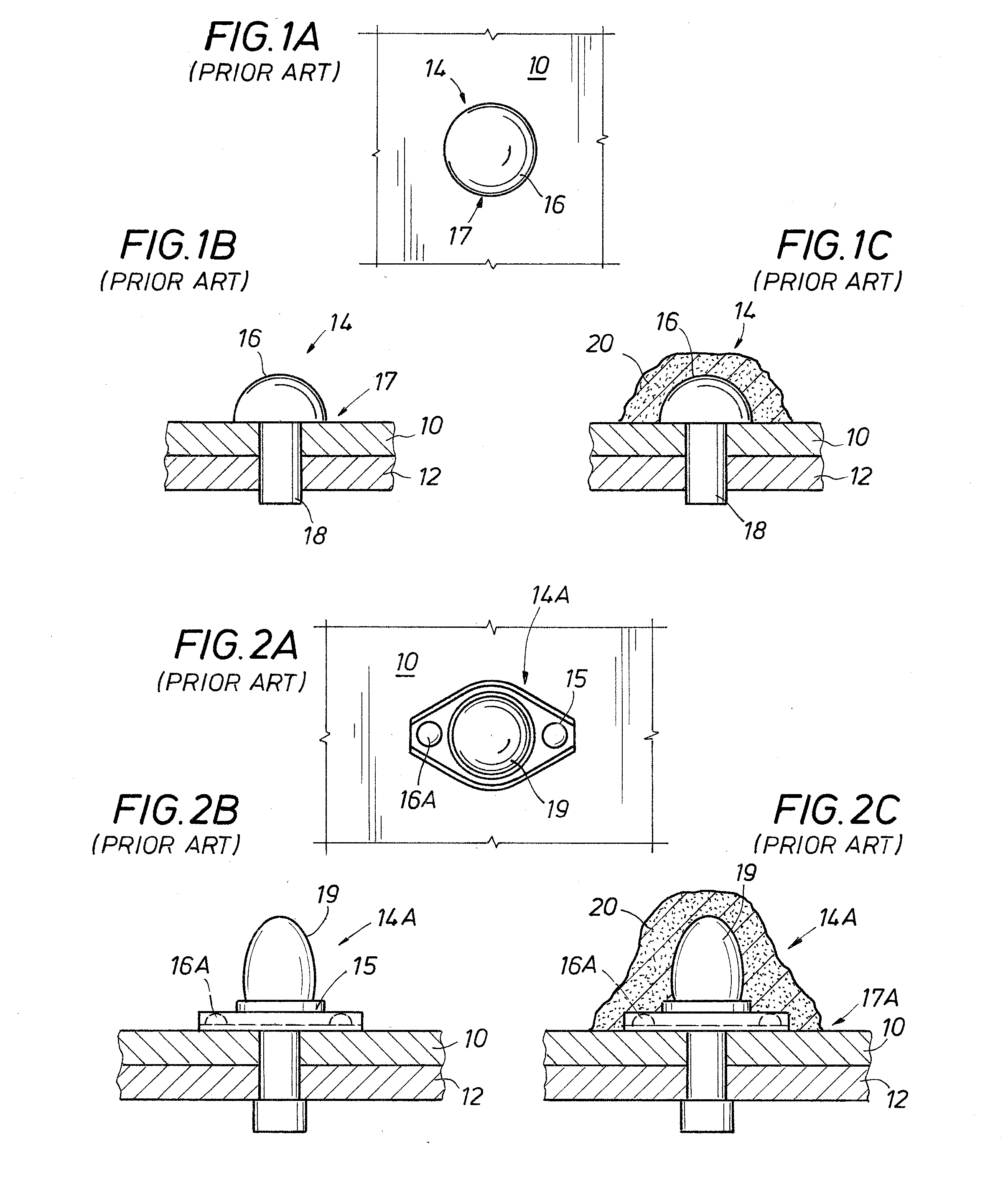
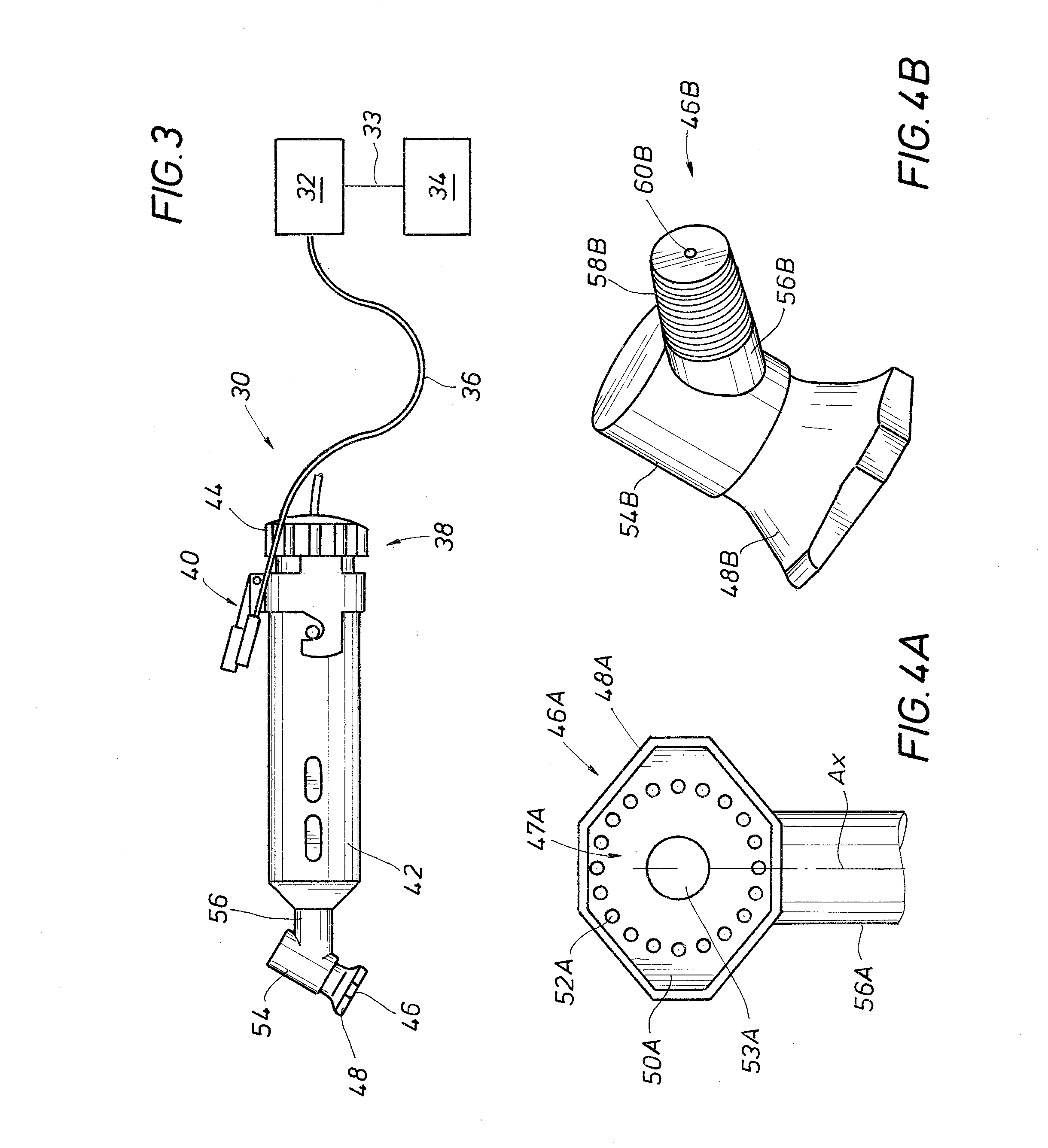
BACKGROUND1. Field of InventionThe present disclosure relates generally to a nozzle for dispensing sealant on aircraft fasteners. More specifically, the present disclosure concerns nozzles adapted to enclose an exposed fastener head and meter an amount of sealant over the fastener head.2. Description of Prior ArtAircraft fuel tanks are typically assembled by fastening together sheets of metal or composite material. Fastening techniques include adhesive compounds, welding, and rivets. Riveting pierces the sheets being fastened thus creating a potential fluid leakage path along the rivet. To prevent leakage across the rivets, a sealant is generally applied along the interface between a fastener head and the exterior of the fuel tank. Referring now to FIG. 1A, a prior art example of a fastener 14 is shown attached to an upper fastened member 10. An interface 17 defines the fastener 14 to upper fastened member 10 contact periphery. Shown in sectional view in FIG. 1B, the fastener 14 inc...

Claims


Application Information

Patent Timeline
IPC IPC(8): B29C45/14
CPCB05C11/1002B05C17/00513B05C17/00516B05C17/00573Y02T50/44B64D37/02B64F5/0009F16B19/008B64C3/34B64F5/10Y02T50/40
Inventor KELLEY, JAMES A.WEAVER, MICHAEL B.
Owner LOCKHEED MARTIN CORP
Why Eureka
Try Eureka