Color temperature tunable white light emitting device

a light emitting device and color temperature technology, applied in the direction of discharge tube luminescnet screens, lighting and heating apparatus, multiple discharge path lamps, etc., can solve the problems of high color temperature, complicated driving circuit design implementation, and high cost and implementation complexity

Active Publication Date: 2011-02-03
NAT TAIWAN UNIV OF SCI & TECH
View PDF13 Cites 23 Cited by
  • Summary
  • Abstract
  • Description
  • Claims
  • Application Information

AI Technical Summary

Benefits of technology

[0012]An exemplary color temperature tunable white light emitting device comprises a substrate with an ultraviolet light-emitting diode (UV LED) disposed thereover, electrically connected to the substrate, wherein the UV LED has a first emission surface for emitting ultraviolet (UV) light. A purple light-emitting diode (purple LED) is disposed over the substrate to electrically connect with the substrate, wherein the purple LED has a second emission surface for emitting purple light. A blue light-emitting diode (blue LED) is disposed over the substrate to electrically connect with the substrate, wherein the blue LED has a third emission surface for emitting blue light. A phosphor layer is coated around the UV LED, the purple LED, and the blue LED, wherein the phosphor layer is formed by blending phosphors of the at least two color phosphors in a transparent optical resin, and the phosphors of the at least two color phosphors in the transparent optical resin are excited by the UV light from the UV LED and the purple light from the purple LED to thereby emit visible light. The blue light from the blue LED combines with the visible light from the phosphors to emit white light. An omni-directional reflector is disposed over the phosphor layer and opposite to the first emission surface of the UV LED, the second emission surface of the purple LED, and the third emission surface of the blue LED. A medium layer is disposed between the omni-directional reflector and the phosphor layer, wherein the medium layer has a refractive index that is less than a refractive index of the phosphor layer and the omni-directional reflector. A transparent substrate is disposed over the omni-directional reflector, wherein the transparent substrate has opposite first and second surfaces, and the first surface of the transparent substrate is in contact with the omni-directional reflector. An optical diffuser is disposed over the second surface of the transparent substrate.
[0013]Another exemplary color temperature tunable white light emitting device comprise a substrate with a pair of first metal pins, a pair of second metal pins, and a pair of third meta pins disposed along opposite ends of the substrate, respectively. An ultraviolet light-emitting diode (UV LED) is disposed over the substrate to electrically connect with the pair of first metal pin, wherein the UV LED has a first emission surface for emitting ultraviolet (UV) light. A purple light-emitting diode (purple LED) is disposed over the substrate to electrically connect with the pair of second metal pin, wherein the purple LED has a second emission surface for emitting purple light. A blue light-emitting diode (blue LED) is disposed over the substrate to electrically connect with the pair of third metal pin, wherein the blue LED has a third emission surface for emitting blue light. A transparent layer is coated around the UV LED, the purple LED, and the blue LED, wherein the transparent layer comprise materials that are transparent to the UV light, the purple light and the blue light. A phosphor layer is formed over the transparent layer, wherein the phosphor layer is formed by blending phosphors of the at least two colors in a transparent optical resin, and the phosphors of the at least two colors in the transparent optical resin are excited by the UV light from the UV LED and the purple light from the purple LED to thereby emit visible light. The blue light from the blue LED combines with the visible light from the phosphors to emit white light. An omni-directional reflector is disposed over the phosphor layer and opposite to the first emission surface of the UV LED, the second emission surface of the purple LED, and the third emission surface of the blue LED. A medium layer is disposed between the omni-directional reflector and the phosphor layer, wherein the medium layer has a refractive index that is less than that of the phosphor layer. A transparent substrate is disposed over the omni-directional reflector, wherein the transparent substrate has opposite first and second surfaces, and the first surface of the transparent substrate is in contact with the omni-directional reflector. An optical diffuser is disposed over the second surface of the transparent substrate.

Problems solved by technology

However, tri-color LED (red, blue and green LED) with different epitaxial materials exhibit different electrical and aging properties, resulting in high cost and complicated driving circuit design for implementation.
Also, there is an issue of non-uniform spatial distribution of white light for mixing trichromatic light due to the placement of tri-color LEDs.
However, the method wherein the white LED uses the blue LED to excite the yellow phosphors has some drawbacks.
First, the large amount of transmitted blue light power result in high color temperatures and non-uniform white light distribution.
Second, the wavelength of blue light shifts with the LED junction temperature rises, resulting in changes of chromaticity coordinates of the emitted white light.
Third, due to the predetermined admixing ratio between yellow phosphor and optical resin of the phosphor resin layer, the color temperature of the white light mixing blue and yellow light is fixed and with limited color temperature tunability.
However, the method wherein the white LED uses the UV or purple LED to excite the multi-color phosphor has some drawbacks.
First, there is a leakage of the purple light or UV light, and this limits its applications.
Second, the fixed color temperature of the emitted white light results from the predetermined phosphors in resin ratio, and can not be tuned in real time.
Second, the color temperature of the emitted white light can not be tuned in real time.
Third, the light distribution of the mixing white light is non-uniform.
Thus, the color temperature of the white light cannot be tuned for lighting applications, and according to the user preference or requirements of lighting applications

Method used


Image

  • Color temperature tunable white light emitting device
  • Color temperature tunable white light emitting device
  • Color temperature tunable white light emitting device

Examples


example

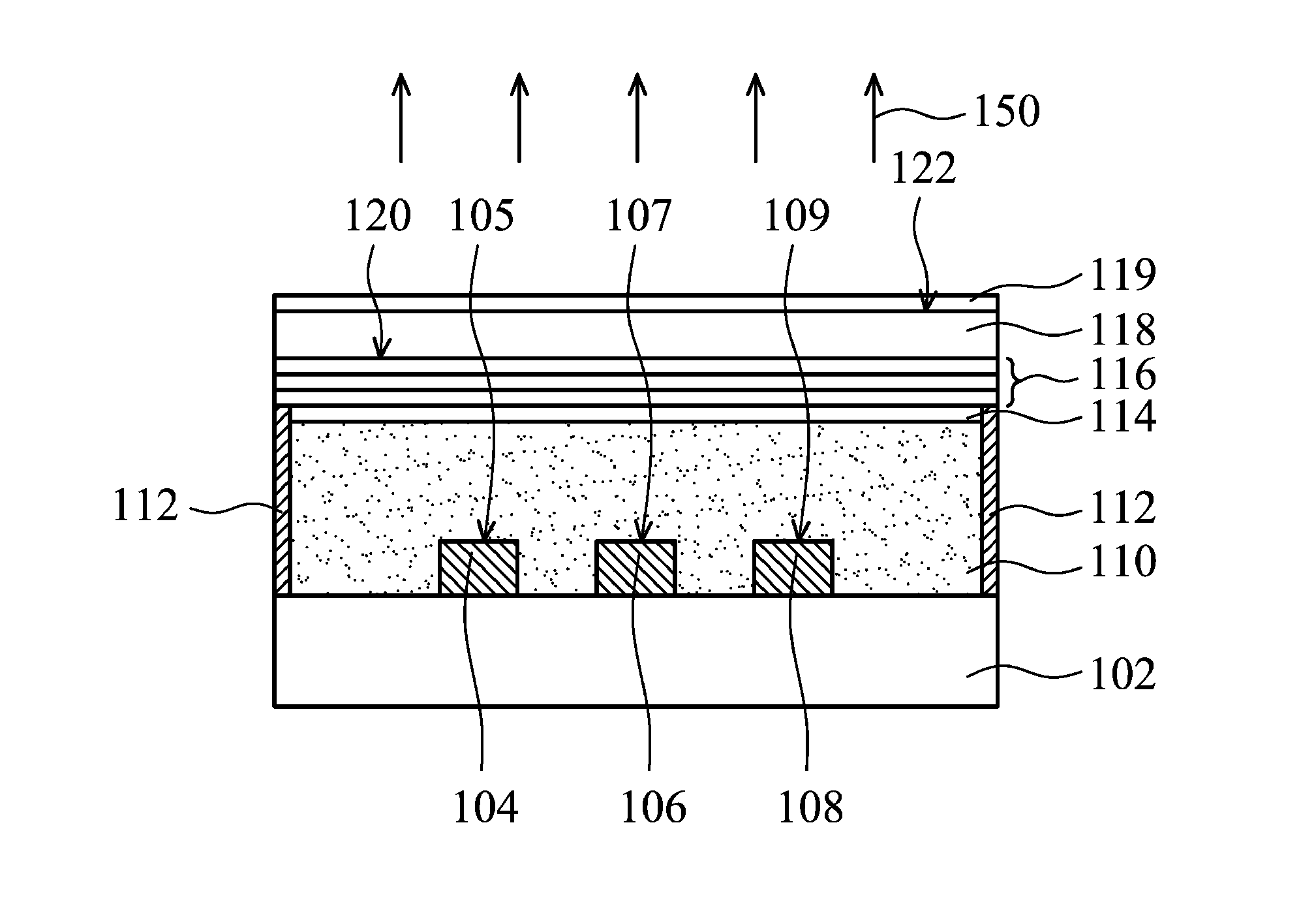
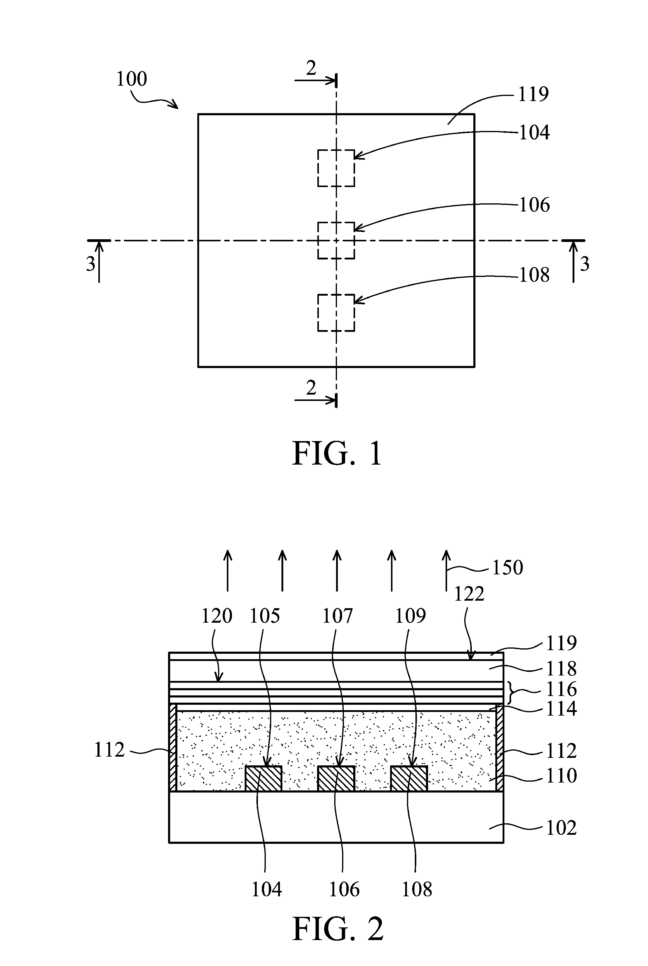
[0046]The white light emitting device 300 illustrated in FIGS. 6-7 was carried out for demonstration. The white light emitting device 300 was provided with a UV LED 104 made of an InGaN chip for emitting UV light having a wavelength of about 372 nm, a purple LED 106 made of an InGaN chip for emitting purple light having a wavelength of about 412 nm, and a blue LED 108 made of an InGaN chip for emitting blue light having a wavelength of about 460 nm. The phosphor layer 110 was provided with phosphors of red and green colors, and the UV LED 104, the purple LED 106 and blue LED 108 were driven by different driving currents to thereby obtain the measured results showing color gamut and color temperature of the color temperature tunable white light emitting device 300. Table 1 shows the experimental results in the demonstration.

TABLE 1OperatingOperatingOperatingcurrent of UVcurrent ofcurrent ofColorColorColorLED 104purple LEDblue LEDcoordinatecoordinateTemperature(mA)106 (mA)108 (mA)(x)(...


PUM


Abstract

A color temperature tunable white light emitting device is provided, including a substrate with an ultraviolet light emitting diode, a purple light emitting diode, and a blue light emitting diode provided over the substrate. The UV LED, the purple LED and the blue LED are coated with a phosphor layer. An omnidirectional reflector is disposed over the phosphor layer. A medium layer is disposed between the omni-directional reflector and the phosphor layer. A transparent substrate is disposed over the omnidirectional reflector and an optical diffuser is disposed over the transparent substrate.

Description

CROSS REFERENCE TO RELATED APPLICATIONS[0001]This application claims priority of Taiwan Patent Application No. 98125802, filed on Jul. 31, 2009, the entirety of which is incorporated by reference herein.BACKGROUND OF THE INVENTION[0002]1. Field of the Invention[0003]The present invention relates to light emitting devices, and in particular, to a white light-emitting device capable of emitting white light with color temperature tunability.[0004]2. Description of the Related Art[0005]White light-emitting diodes (LEDs) are point light sources that are packaged as a matrix LED for illumination. White light is produced by combining at least two chromatic lights with different wavelengths, such as a blue and yellow light of complementary color or a blue, green and red light.[0006]There are three types of white LEDs presently available. One type uses a white light LED module composed of red, blue and green LEDs, with high luminous efficacy, high color rendering, and real-time tunable color...

Claims


Application Information

Patent Timeline
Patent Type & Authority Applications(United States)
IPC IPC(8): H01J1/62
CPCH01L25/0753H01L33/50H01L2224/48091H01L2224/48247H01L2924/00H01L2924/00014
Inventor SU, JUNG-CHIEHLU, CHUN-LIN
Owner NAT TAIWAN UNIV OF SCI & TECH
Why Eureka
Try Eureka