Color-coded backlighted single camera three-dimensional defocusing particle image velocimetry system

Inactive Publication Date: 2011-02-03
UNIV OF WASHINGTON
View PDF6 Cites 52 Cited by
  • Summary
  • Abstract
  • Description
  • Claims
  • Application Information

AI Technical Summary

Benefits of technology

[0008]This summary is provided to introduce a selection of concepts in a simplified form that are further described below in the Detailed Description. This summary i

Problems solved by technology

An error analysis with an uncertainty test was also reported.
Using this three-camera 3DDPIV system to measure velocities within small-scale flow fields has two major difficulties.
First, due to its size and complexity, this type of system is hard to setup and calibrate.
Second, with the presence of the pinhole mask, a high intensity light source is required to adequately illuminate the flow, which can noticeably

Method used


Image

  • Color-coded backlighted single camera three-dimensional defocusing particle image velocimetry system
  • Color-coded backlighted single camera three-dimensional defocusing particle image velocimetry system
  • Color-coded backlighted single camera three-dimensional defocusing particle image velocimetry system

Examples


Embodiment Construction

reciated as the same become better understood by reference to the following detailed description, when taken in conjunction with the accompanying drawings, wherein:

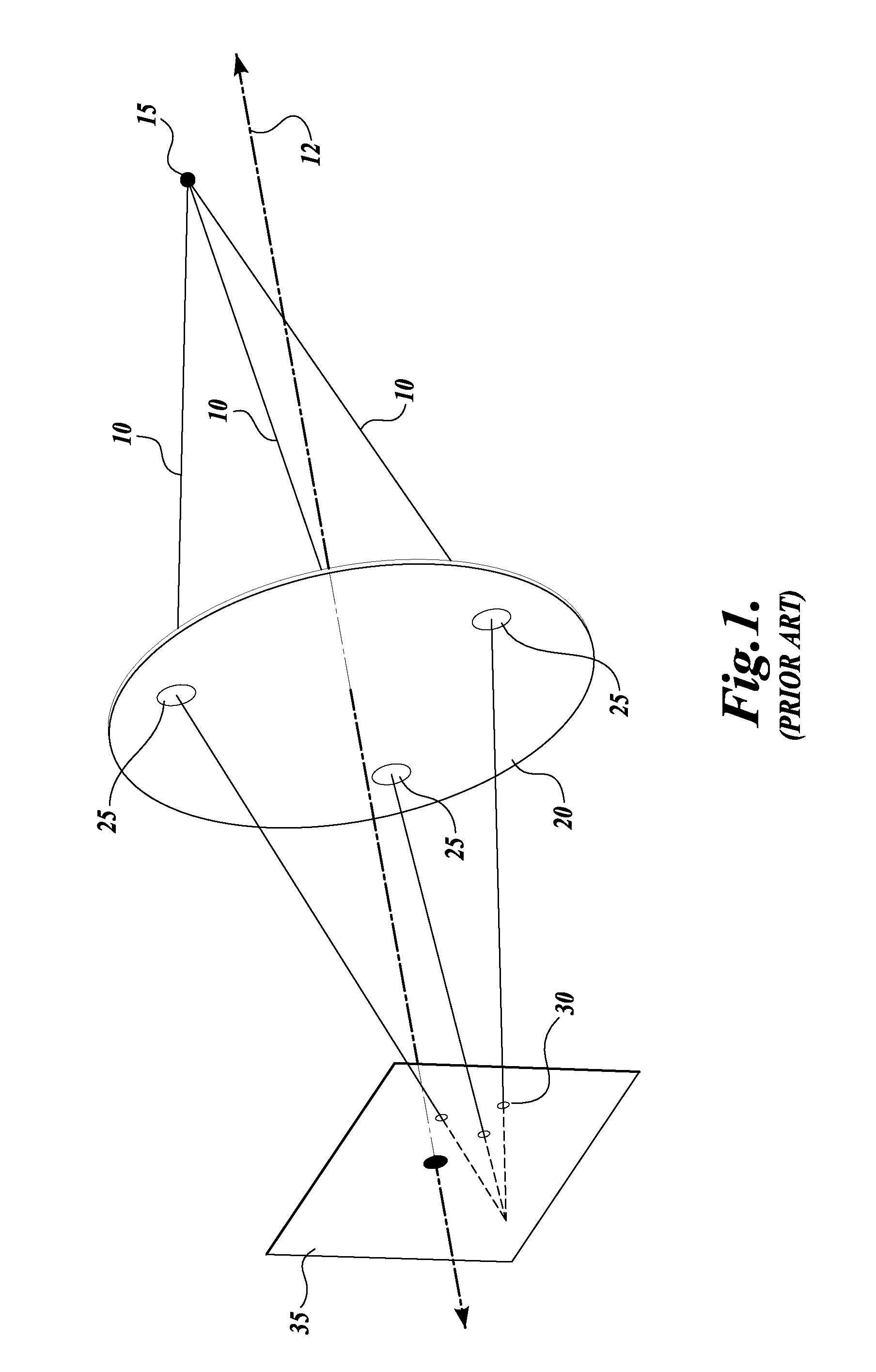
[0012]FIG. 1 is a diagram illustrating schematically a conventional 3DDPIV system;

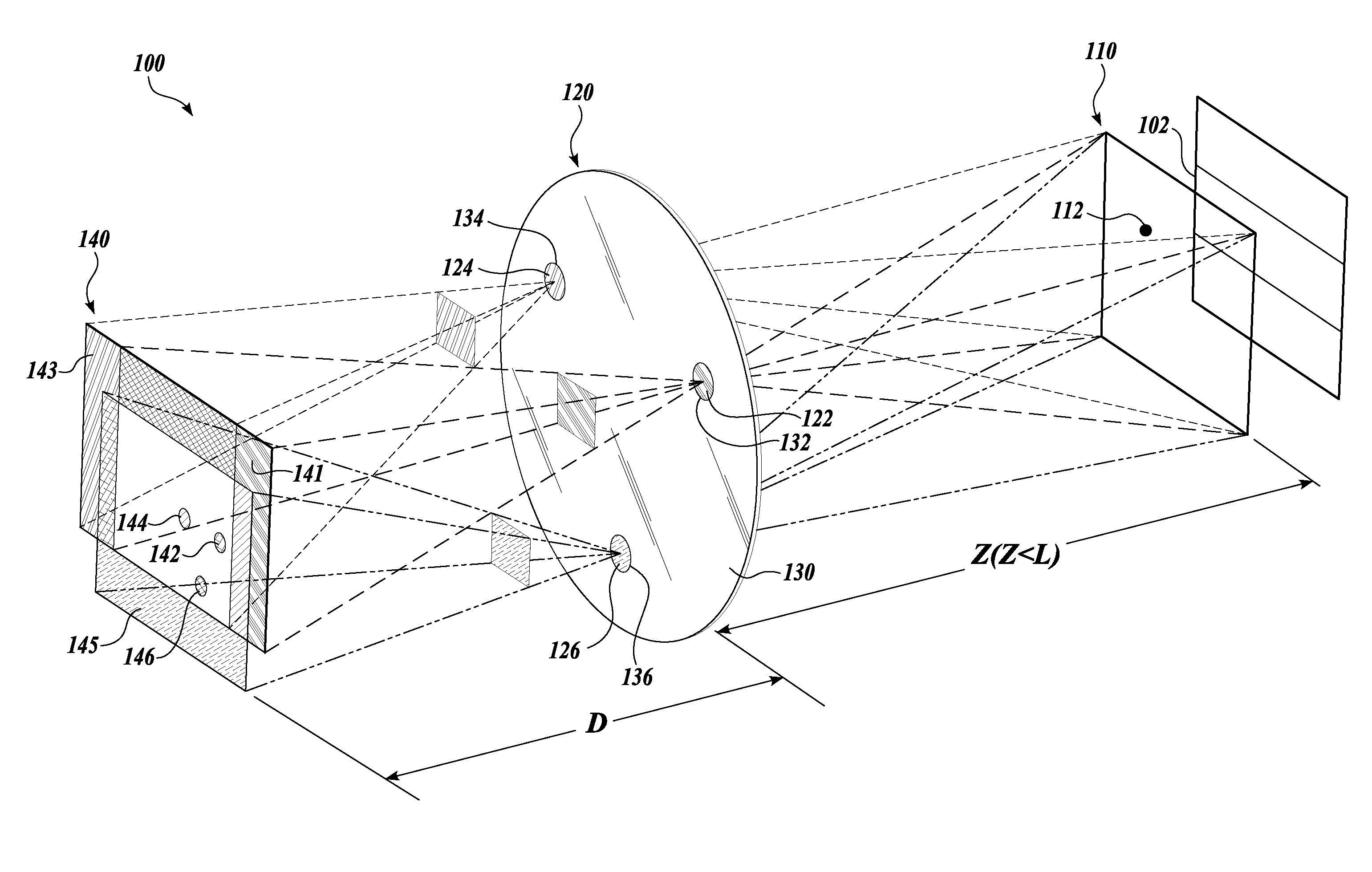
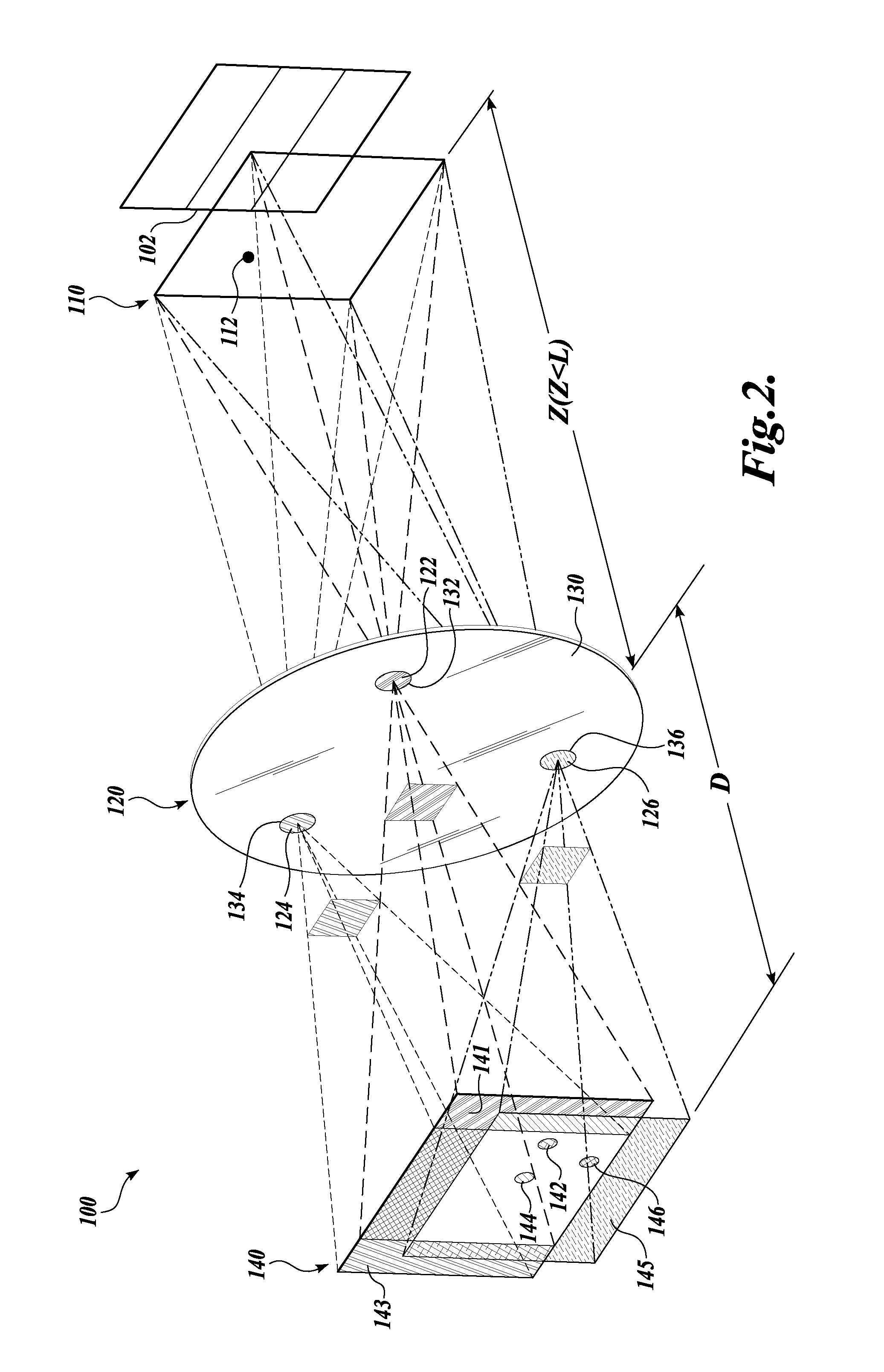
[0013]FIG. 2 is a diagram illustrating the basic operation of a color-coded backlighted single camera 3DDPIV system in accordance with the present invention;

[0014]FIGS. 3A and 3B illustrate the resulting image on the CCD plane when no color filters are used (3A) and when color filters are used (3B) in combination with backlighting; and

[0015]FIG. 4 is a diagram illustrating an apparatus for implementing the 3DDPIV illustrated in FIG. 2, using color filters, backlighting and a single camera for performing three-dimensional defocusing particle image velocimetry.

DETAILED DESCRIPTION

[0016]A system and method will now be described for conducting color-coded and backlighted 3DDPIV, with reference to the figures wherein like numbers indicate like el...


PUM


Abstract

Three-Dimensional Defocusing Particle Image Velocimetry (3DDPIV) allows for measurement of three-dimensional velocities within a volume. In the disclosed embodiment, a mask with a plurality of apertures is disposed with a lens between the test section and a color camera. The field-of-view is backlit and the test section is seeded with black particles. This configuration allows for a lower power light source as compared to conventional 3DDPIV. Color-coded particle images are formed on a white background, wherein each of the color images is generated from light that travels through the filters not blocked by the imaged particle, thereby producing a color image that is of a color different from the color of any of the filters. A color space linear transformation is used to allow for accurate identification of each pinhole exposure when the color filters' spectrum does not match those of the 3-CCD color camera.

Description

CROSS-REFERENCES TO RELATED APPLICATIONS[0001]This application is a continuation of International Application No. PCT / US2008 / 076562, filed Sep. 16, 2008, which claims the benefit of U.S. Provisional Application No. 60 / 973,331, filed Sep. 18, 2007. Each application is expressly incorporated herein by reference in its entirety.STATEMENT OF GOVERNMENT LICENSE RIGHTS[0002]This invention was made with Government support under Government Contract No. 5R01RR023190 awarded by the National Institutes of Health. The Government has certain rights in the invention.BACKGROUND[0003]Particle image velocimetry (“PIV”), including digital particle image velocimetry (“DPIV”), has become a widely used quantitative flow visualization technique in fluid mechanics research due to its ability to provide non-intrusive, highly resolved measurement of planar velocity fields. With the use of ever-advancing CCD cameras, digital data acquisition systems, and sophisticated algorithms, DPIV continues to evolve and...

Claims


Application Information

Patent Timeline
IPC IPC(8): H04N13/02
CPCG01N2015/1075G01P5/20G01P5/001
Inventor DABIRI, DANATIEN, WEI-HSINKARTES, PATRICKYAMASAKI, TORU
Owner UNIV OF WASHINGTON
Why Eureka
Try Eureka