
Image processing apparatus and method

Active Publication Date: 2011-02-03
SONY CORP
View PDF7 Cites 69 Cited by
  • Summary
  • Abstract
  • Description
  • Claims
  • Application Information

AI Technical Summary

Benefits of technology

[0011]The above-described control block is arranged as a reference in a predetermined position with respect to an image. However, the arrangement of the control block may not be typically optimum, in the contents of the image or the encoding processing method, and thus it may unnecessarily reduce the effect of the filter process, or unnecessarily reduce the encoding efficiency.
[0012]For example, if the characteristic of an image is greatly changed in the control block, the effect of the filter Process may deteriorate in comparison to a case where the characteristic of an image is uniform in the control block. Also, there is a method (multi-slice) of dividing one frame into a plurality of slices and performing an encoding or decoding process of image with respect to the divided slices. If the control block is positioned to extend over a plurality of slices, for the filter process, for example, the plurality of slices should be processed or dummy data should be generated, so that the process may be complicated or delay time may be increased. Also, due to this, the effect of the filter process may be reduced. Further, in the case where control information for the filter process is included in image compression information, unnecessary control information is increased, and this may cause the encoding efficiency to be reduced.

Problems solved by technology

However, the arrangement of the control block may not be typically optimum, in the contents of the image or the encoding processing method, and thus it may unnecessarily reduce the effect of the filter process, or unnecessarily reduce the encoding efficiency.
For example, if the characteristic of an image is greatly changed in the control block, the effect of the filter Process may deteriorate in comparison to a case where the characteristic of an image is uniform in the control block.
If the control block is positioned to extend over a plurality of slices, for the filter process, for example, the plurality of slices should be processed or dummy data should be generated, so that the process may be complicated or delay time may be increased.
Further, in the case where control information for the filter process is included in image compression information, unnecessary control information is increased, and this may cause the encoding efficiency to be reduced.
Further, even the size of the control block or the filter coefficient may not be typically appropriate with respect to the image.

Method used


Image

  • Image processing apparatus and method
  • Image processing apparatus and method
  • Image processing apparatus and method

Examples


first embodiment

1. First Embodiment

[Configuration of a Device]

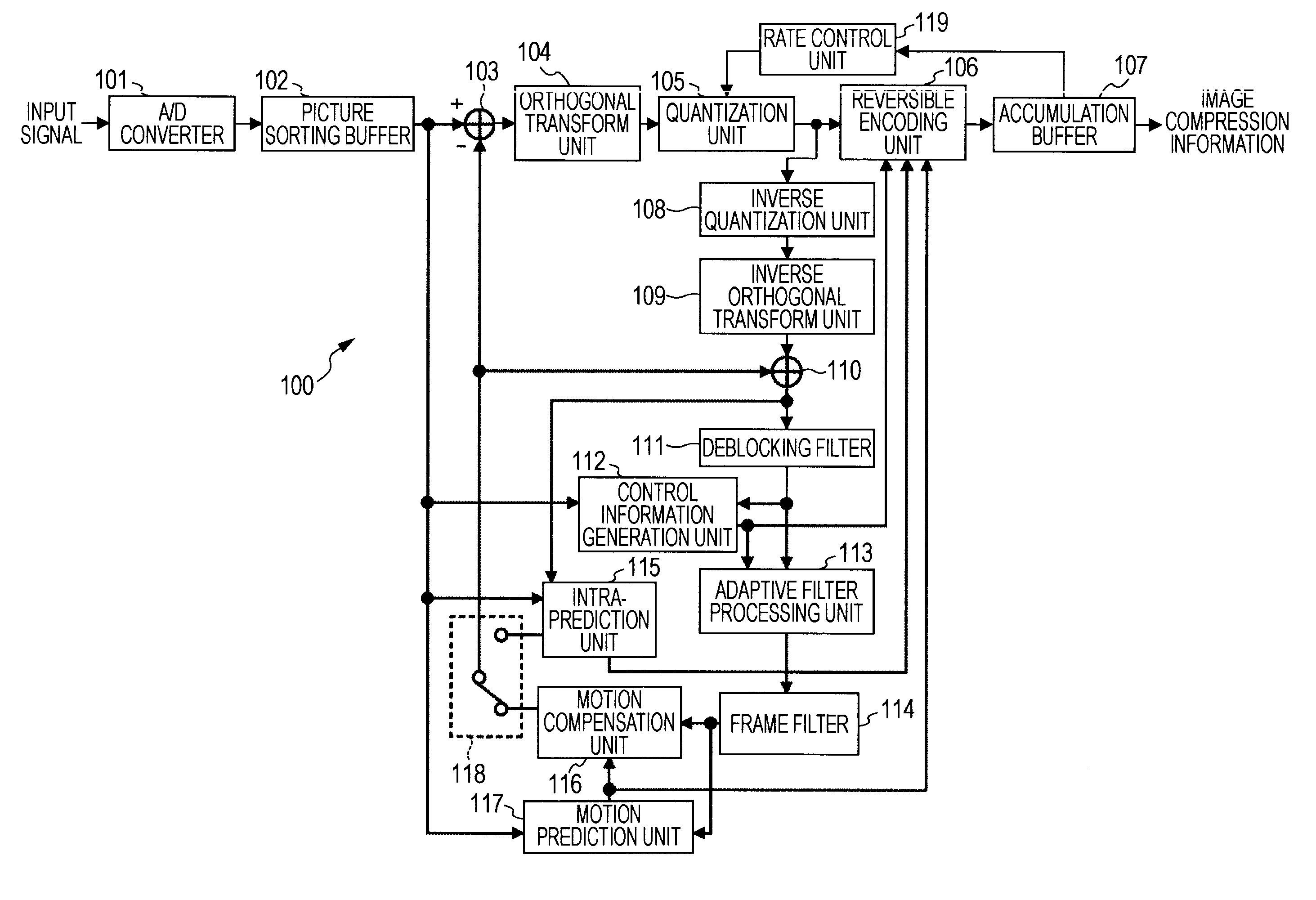
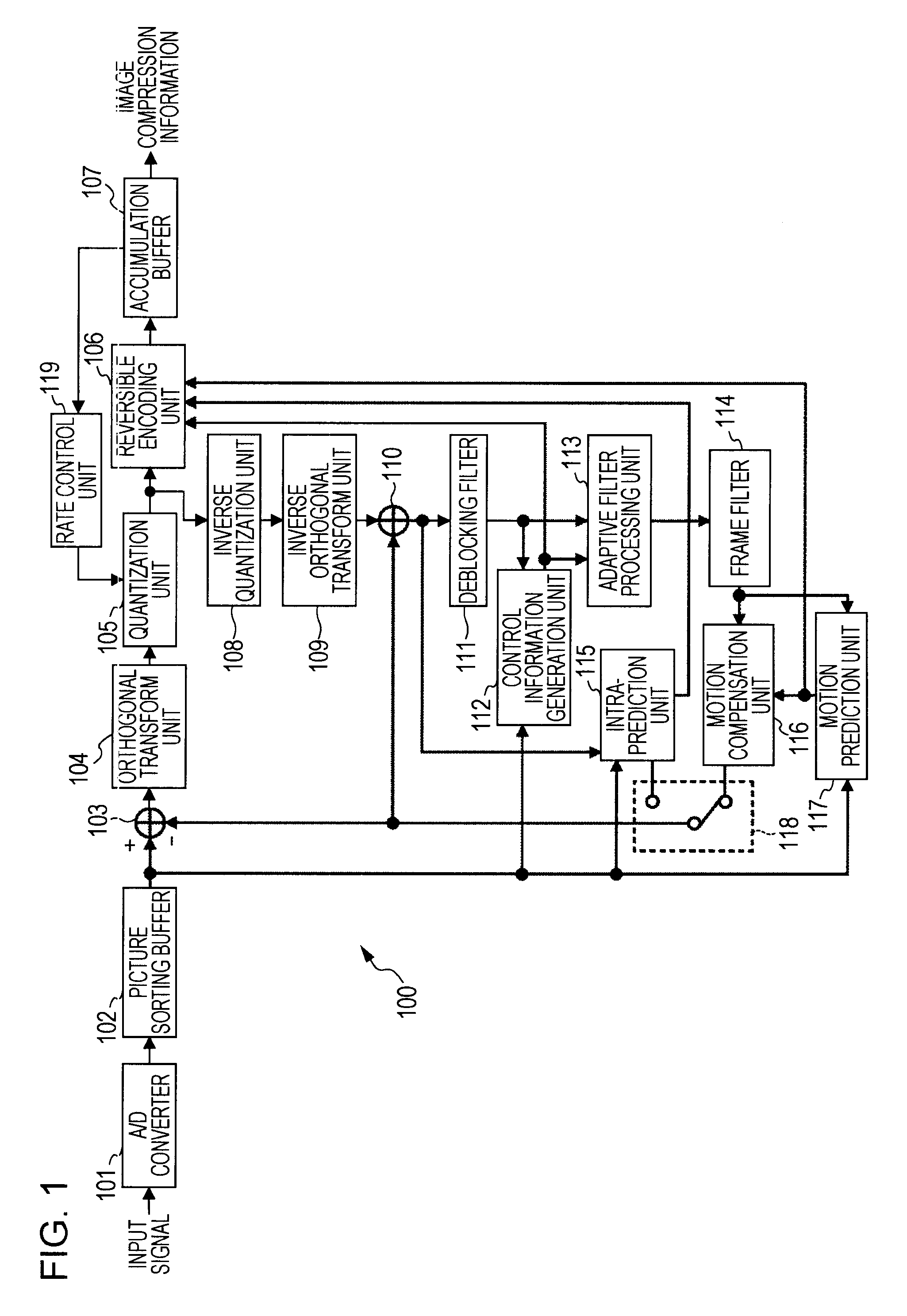
[0076]FIG. 1 is a block diagram illustrating a configuration example of an image encoding apparatus as an image processing apparatus to which the present invention is applied.

[0077]An image encoding apparatus 100 as illustrated in FIG. 1 is an encoding apparatus that compresses and encodes an image, for example, in the H.264 and MPEG-4 Part 10 (Advanced Video Coding) (hereinafter described as “H.264 / AVC”) method, and further adopts an adaptive loop filter.

[0078]In an example of FIG. 1, the image encoding apparatus 100 includes an A / D (Analog / Digital) conversion unit 101, a picture sorting buffer 102, an operation unit 103, an orthogonal transform unit 104, a quantization unit 105, a reversible encoding unit 106, and an accumulation buffer 107. Also, the image encoding apparatus 100 includes an inverse quantization unit 108, an inverse orthogonal transform unit 109, an operation unit 110, and a deblocking filter 111. Further, the image en...

second embodiment

2. Second Embodiment

[0232][Configuration of a Device]

[0233]Next, an image decoding apparatus that corresponds to the image encoding apparatus 100 as described above with reference to FIG. 1 will be described. FIG. 17 is a block diagram illustrating a configuration example of an image decoding apparatus as an image processing apparatus to which the present invention is applied.

[0234]An image decoding apparatus 200 generates a decoded image by decoding the image compression information output from the image encoding apparatus 100.

[0235]The image decoding apparatus 200 includes an accumulation buffer 201, a reversible decoding unit 202, an inverse quantization unit 203, an inverse orthogonal transform unit 204, an operation unit 205, and a deblocking filter 206. Also, the image decoding apparatus 200 includes an adaptive filter processing unit 207. Further, the image decoding apparatus 200 includes a picture sorting buffer 208, and a D / A (Digital / Analog) conversion unit 209. Also, the ...

third embodiment

3. Third Embodiment

[0268][Another Example of an Alf Block to be Processed]

[0269]As described above, it is exemplified that the control information generation unit 112 generates the filter block flag with respect to all the ALF blocks that include even a small portion of the region of the slice to be processed, and the adaptive filter processing unit 113 performs the filter orocess with respect to all the ALF blocks that include even a small portion of the slice to be processed.

[0270]However, for example, if the region of the slice to be processed that is included in the ALF block is only one pixel, the filter process exerts almost no influence upon the picture quality of the slice to be processed. In this case, even if the filter process is performed with respect to the ALF block having a low rate of the region of the slice to be processed, sufficient effect may not be obtained and the processing (load) may be unnecessary.

[0271]Accordingly, the filter process may be performed with r...


PUM


Abstract

Provided is an image processing apparatus which includes a setting unit assigning a control block, which is a control unit of a filter process that is locally performed with respect to an image, to an initial position of the image determined based on a predetermined reference point; a movement unit moving the control block, which has been assigned to the initial position of the image by the setting unit, a to a position in which the result of the filter process is improved; and a filter processing unit performing the filter process for the respective control blocks which has been moved by the movement unit.

Description

BACKGROUND OF THE INVENTION[0001]1. Field of the Invention[0002]The present invention relates to an image processing apparatus and method. In particular, the present invention relates to an image processing apparatus and method, which can more appropriately perform a local control of a filter process during an encoding or decoding operation.[0003]2. Description of the Related Art[0004]Recently, devices complied with an MPEG (Moving Picture Experts Group) system or the like, which manage image information as digital information, and compress, for the purpose of transmitting and accumulating information having high efficiency, the image information by an orthogonal transform such as a discrete cosine transform and motion compensation using redundancy peculiar to the image information, have been widely used on both sides of a broadcasting station for transferring the information and general home for receiving the information.[0005]In particular, MPEG-2 (ISO (International Organization ...

Claims


Application Information

Patent Timeline
IPC IPC(8): H04N7/12H04N19/00H04N19/117H04N19/146H04N19/154H04N19/174H04N19/19H04N19/196H04N19/46H04N19/503H04N19/51H04N19/593H04N19/61H04N19/625H04N19/70H04N19/82H04N19/86H04N19/91H04N19/96
CPCH04N19/70H04N19/172H04N19/86H04N19/127H04N19/82H04N19/117
Inventor KENJI, KONDO
Owner SONY CORP
Learn More