Refrigeration apparatus
a technology of refrigerating apparatus and refrigeration machine, which is applied in the direction of refrigeration machine, corrosion prevention, gas cycle refrigeration machine, etc., can solve the problems of inability to improve the defrosting capacity and the temperature drop on the indoor sid
- Summary
- Abstract
- Description
- Claims
- Application Information
AI Technical Summary
Benefits of technology
Problems solved by technology
Method used
Image
Examples
modification 1
(3) Modification 1
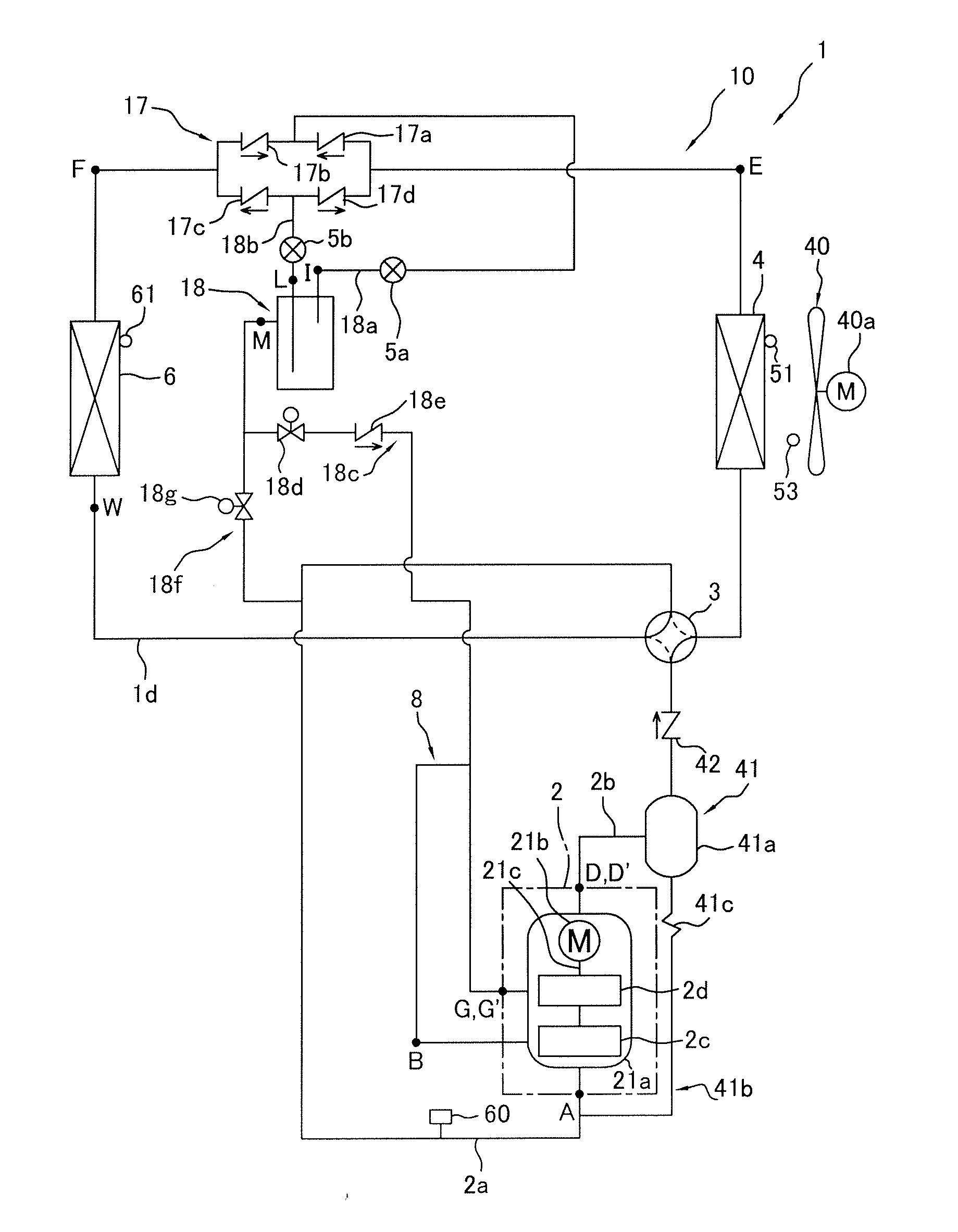
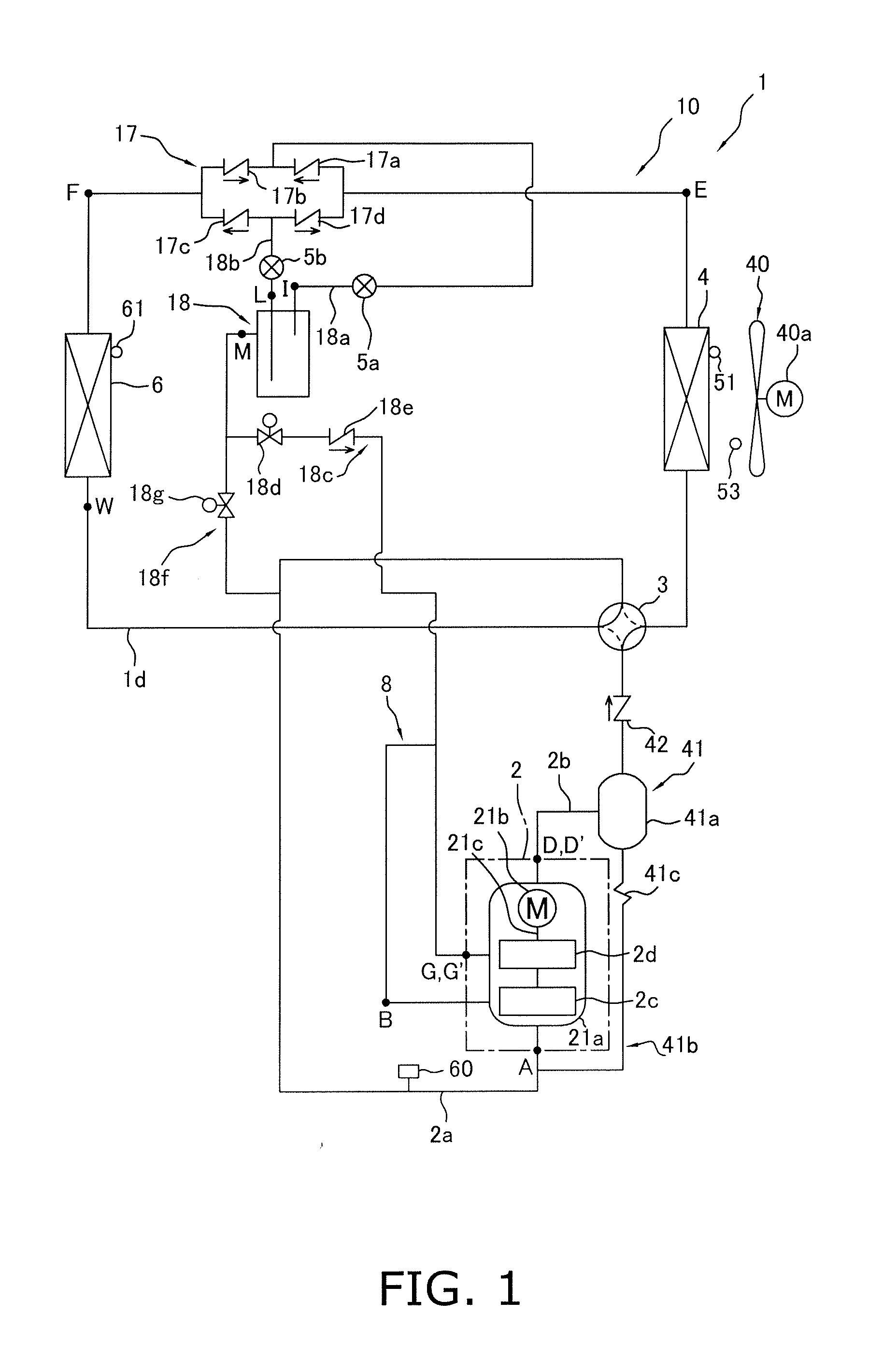
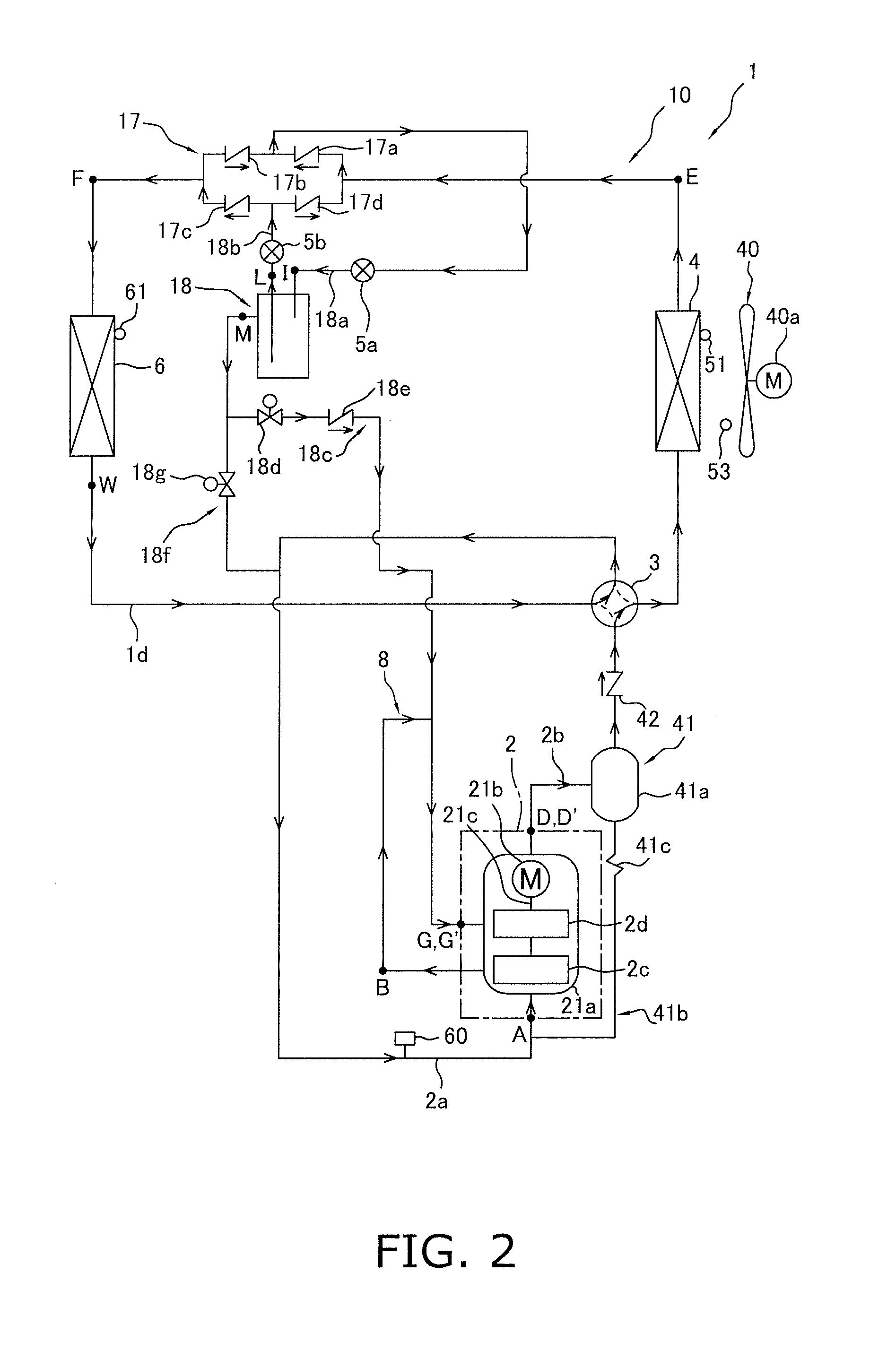
[0094]In the embodiment described above, in the air-conditioning apparatus 1 configured to be capable of switching between the air-cooling operation and the air-warming operation via the switching mechanism 3, the first second-stage injection tube 18c is provided for performing intermediate pressure injection through the receiver 18 as a gas-liquid separator, and intermediate pressure injection is performed by the receiver 18 as a gas-liquid separator, but instead of intermediate pressure injection by the receiver 18, another possible option is to provide a second second-stage injection tube 19 and an economizer heat exchanger 20 and to perform intermediate pressure injection through the economizer heat exchanger 20.
[0095]For example, as shown in FIG. 10, a refrigerant circuit 110 can be used which is provided with a second second-stage injection tube 19 and an economizer heat exchanger 20 instead of the first second-stage injection tube 18c in the embodiment descr...
modification 2
(4) Modification 2
[0118]In the refrigerant circuits 10 and 110 (FIGS. 1 and 10) in the embodiment and Modification 1 described above, intermediate pressure injection by the receiver 18 as a gas-liquid separator or intermediate pressure injection by the economizer heat exchanger 20 is performed, whereby the temperature of the refrigerant discharged from the second-stage compression element 2d is reduced, the power consumption of the compression mechanism 2 is reduced, and operating efficiency is improved, but in addition to this configuration, the intermediate refrigerant tube 8 for drawing the refrigerant discharged from the first-stage compression element 2c into the second-stage compression element 2d may also be provided with an intermediate heat exchanger 7 that functions as a cooler of refrigerant discharged from the first-stage compression element 2c and drawn into the second-stage compression element 2d.
[0119]For example, the refrigerant circuit 110 of Modification 1 describ...
modification 3
(5) Modification 3
[0144]In the refrigerant circuits 110 and 210 (see FIGS. 10 and 18) in Modifications 1 and 2 described above, in both the air-cooling operation in which the switching mechanism 3 is brought to the cooling operation state and the air-warming operation in which the switching mechanism 3 is brought to the heating operation state, the temperature of the refrigerant discharged from the second-stage compression element 2d is reduced, the power consumption of the compression mechanism 2 is reduced, and operating efficiency can be improved by performing intermediate pressure injection by the economizer heat exchanger 20 as described above. The intermediate pressure injection by the economizer heat exchanger 20 is believed to be beneficial in a refrigerant circuit configuration having a single usage-side heat exchanger 6, wherein the pressure difference from the high pressure in the refrigeration cycle to the nearly intermediate pressure of the refrigeration cycle can be us...
PUM
 Abstract
Description
Claims
Application Information
 - R&D
- Intellectual Property
- Life Sciences
- Materials
- Tech Scout
- Unparalleled Data Quality
- Higher Quality Content
- 60% Fewer Hallucinations
Browse by: Latest US Patents, China's latest patents, Technical Efficacy Thesaurus, Application Domain, Technology Topic, Popular Technical Reports.
© 2025 PatSnap. All rights reserved.Legal|Privacy policy|Modern Slavery Act Transparency Statement|Sitemap|About US| Contact US: help@patsnap.com


