Ultrasound inspection method and apparatus

a technology of ultrasonic and component inspection, applied in the direction of material analysis using sonic/ultrasonic/infrasonic waves, measurement devices, instruments, etc., can solve the problems of unreliable detection of defects such as defects in conventional ultrasonic immersion techniques, labour-intensive and time-consuming, and the difficulty of detecting defects b>5/b> by the ultrasonic measurement system

Inactive Publication Date: 2011-02-10
AIRBUS UK
View PDF10 Cites 11 Cited by
  • Summary
  • Abstract
  • Description
  • Claims
  • Application Information

AI Technical Summary

Problems solved by technology

As a result the defect 5 becomes difficult to detect by the ultrasonic measurement system.
For this reason, conventional ultrasonic immersion techniques can be unreliable for detecting such defects.
However this can be labour intensive and time consuming.
However, this can be expensive and requires a specially trained operator.

Method used


Image

  • Ultrasound inspection method and apparatus
  • Ultrasound inspection method and apparatus
  • Ultrasound inspection method and apparatus

Examples


Embodiment Construction

)

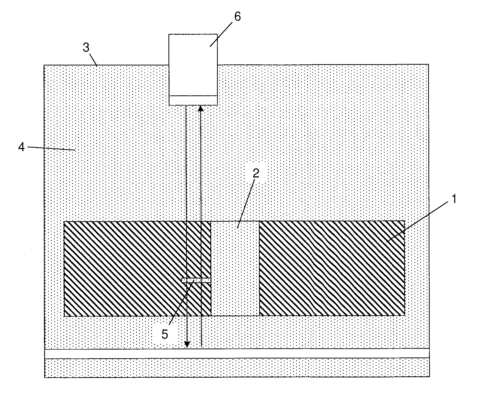
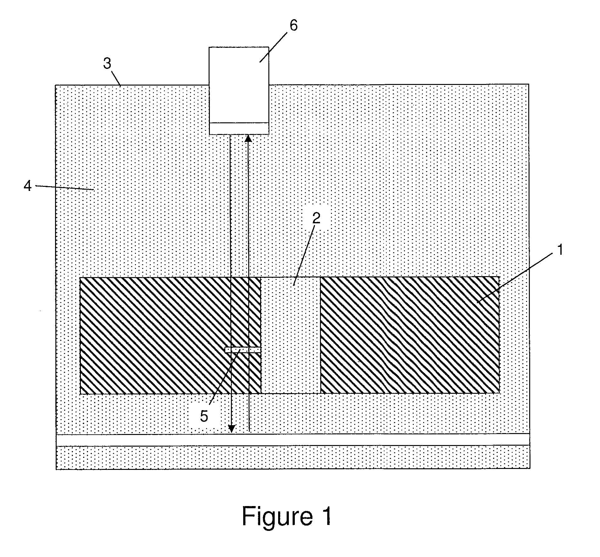
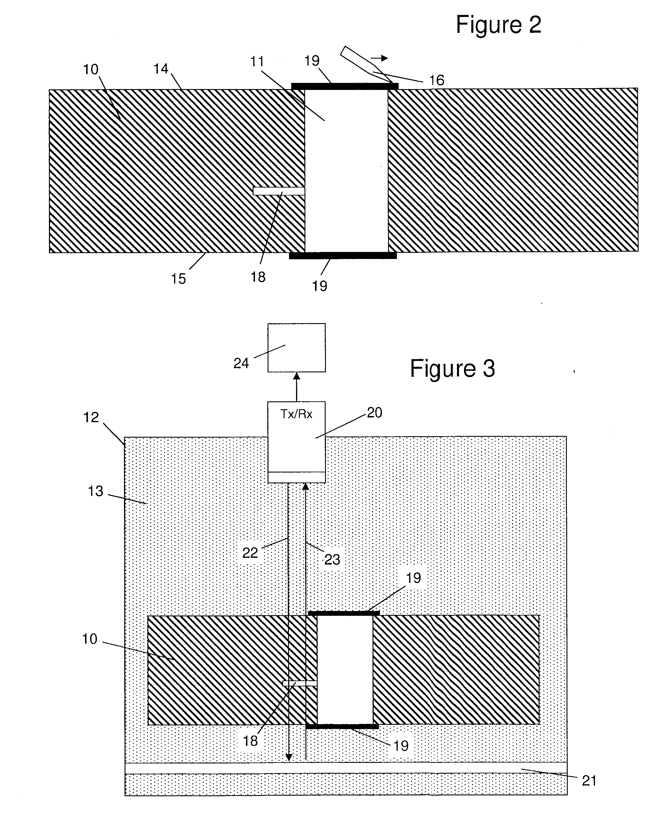
[0021]FIG. 2 shows a composite component 10 comprising a drilled hole 11 which passes vertically through the component 10, penetrating both its upper and lower surfaces 14, to produce upper and lower entrances. The component 10 is made from a Carbon Fibre Reinforced Plastic (CFRP) composite material, with plies of the material terminating at the hole 11. A delamination defect 18 is shown emanating from the side of the hole 11.

[0022]Tape 19 is applied to seal both the upper and lower entrances of the hole 11. The tape 19 is attached to the upper and lower surfaces 14, 15 of the composite component 10 with a thin layer of water resistant adhesive (not shown). The adhesive used to attach the tape 19 to the component 10 cures at room temperature, which makes the tape 19 easy to apply. After the tape 19 has been applied, a scraper 16 is scraped across it as shown in FIG. 2 to remove air bubbles. The scraper 16 is transparent to enable any air bubbles to be seen by an operator.

[0023]Next...


PUM

PropertyMeasurementUnit
acoustic impedanceaaaaaaaaaa
longitudinal wave velocityaaaaaaaaaa

Abstract

A method of inspecting a component, the component comprising a hole with an entrance. The method comprises: directing ultrasound into the component via a liquid coupling medium; receiving ultrasound from the component via the liquid coupling medium; and processing the received ultrasound to determine a property of the component. The entrance of the hole is sealed with tape to prevent the liquid coupling medium from flowing into the entrance of the hole.The tape has an acoustic impedance within 40% of the acoustic impedance of the liquid coupling medium. By selecting a tape with an acoustic impedance relatively close to that of the liquid coupling medium (which in most cases will be water) the tape is relatively transparent to ultrasound and thus enables at least the presence or absence of a defect in a wall of the hole to be determined.

Description

FIELD OF THE INVENTION[0001]The present invention relates to a method and apparatus for inspecting a component with ultrasound.BACKGROUND OF THE INVENTION[0002]FIG. 1 shows a conventional method of inspecting a composite component 1 with a hole 2. The component 1 is immersed in a tank 3 containing water 4. Ultrasonic energy is emitted from a transducer 6 through the water 4 into the component 1. After passing through the component 1, the ultrasonic energy is directed off a reflector back through the component to the transducer 6. The received ultrasonic energy is processed by an ultrasonic measurement system (not shown) to build up a picture of the internal structure of the component.[0003]A delamination defect 5 emanates from the hole 2. When the component 1 is placed in the tank 3, the water flows 4 into the hole 2 and fills the delamination defect 5. As a result the defect 5 becomes difficult to detect by the ultrasonic measurement system. For this reason, conventional ultrasonic...

Claims


Application Information

Patent Timeline
Patent Type & Authority Applications(United States)
IPC IPC(8): G01N29/28
CPCG01N29/28G01N29/043
Inventor COUSINS, JOHN
Owner AIRBUS UK
Why Eureka
Try Eureka