
Method for Recognizing Theft of a PV Module and a Failure of a Bypass Diode of a PV Module, Corresponding PV Sub-Generator Junction Box, PV Inverter, and Corresponding PV System

a technology of pv module and bypass diode, which is applied in the field of recognizing theft of pv module and failure of pv module, and corresponding pv sub-generator junction box, pv inverter, and corresponding pv system, can solve the problems of high risk of theft of such extensive pv system, high cost of system, and increased theft rate. , to achieve the effect of simple and simpl

Inactive Publication Date: 2011-02-10
SIEMENS AG
View PDF8 Cites 27 Cited by
  • Summary
  • Abstract
  • Description
  • Claims
  • Application Information

AI Technical Summary

Benefits of technology

[0019]It is therefore an object of the invention to provide a simpler and at the same time more reliable method for recognizing the theft of a PV module.
[0020]A further object of the invention is to provide a simpler and at the same time more reliable method for recognizing a failure of a bypass diode in a PV module.
[0025]The major advantage is that any significant change in the test current or the test voltage is a sure indication that tampering is occurring in a respective PV string.
[0033]As a consequence of a special embodiment, the respective string test current is set cyclically in one of the respective strings. As a result, the circuit structure is considerably simplified.
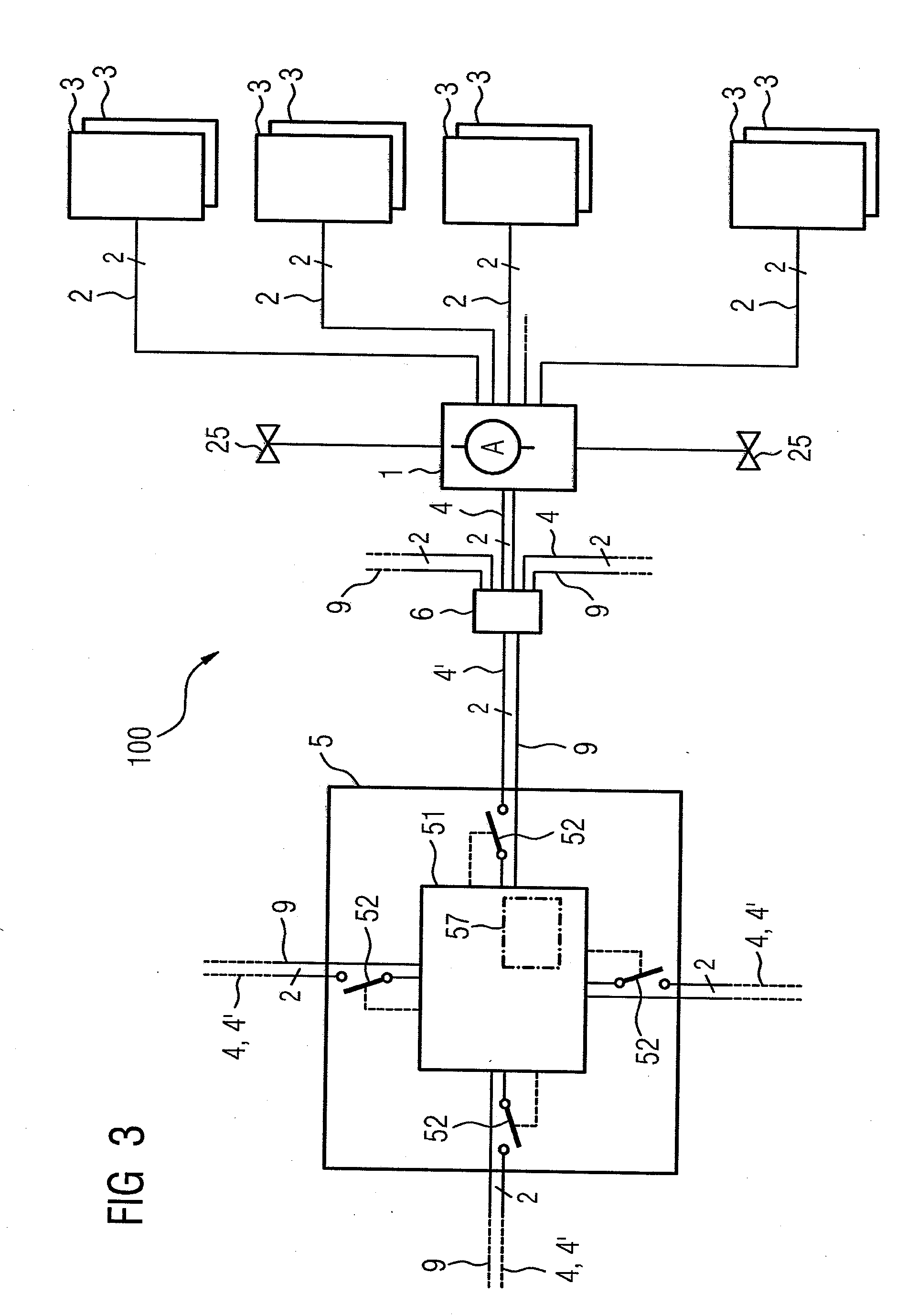
[0038]In particular, the test voltage supply for the electrical supply is connected on the input side to the sub-generator terminal of the PV sub-generator junction box. As a result, it is possible to provide an electrical supply to the inventive PV sub-generator junction box through the central PV inverter.
[0039]In accordance with a particular embodiment, the test voltage supply has an energy store, i.e., an accumulator, which can be charged through the sub-generator terminal. The particular advantage of this embodiment is that interruption-free monitoring of the PV modules and also interruption-free checking of the bypass diodes are possible in the evening and at night, even when the power module of the central PV inverter is switched off. At the commencement of a feeding operation, i.e., typically the following morning, the energy store can be recharged through the sub-generator terminal.

Problems solved by technology

Because of the high unit cost of a PV module of several hundred euros, the risk of theft of such extensive PV systems is especially high.
For some time, as the demand for PV modules has risen, so too has the number of thefts increased sharply.
The consequence is that following a theft of PV modules a number of insurance companies have for their part canceled the policy or have increased the premiums to such an extent that an insurance policy is economically feasible only to a limited extent.
Such systems are, however, on the one hand, very expensive and, on the other hand, error-prone, particularly if wildlife comes into the vicinity of the fence.
Such monitoring systems are, however, easily recognizable and can be easily tampered with, by being bypassed, for example, by “skilled” thieves.
It is disadvantageous that a monitoring of symmetry, however, is no longer possible in the evening or at night due to the lack of presence of a significant string current.
However, by far the most thefts occur directly under the cover of darkness.
In addition, for the operation of a PV system, a recurrent expensive measuring system is required to continuously check the quality of the PV modules.
However, these bypass diodes can become high-impedance or also low-impedance as a result of ageing or lightning damage and thus fail.
As a result, protection of the PV modules is no longer guaranteed, with the result that an entire string of PV modules needs to be switched off in the event of a fault.
On the other hand, the bypass diodes, may short and fail, such as when a thermal overload occurs.

Method used


Image

  • Method for Recognizing Theft of a PV Module and a Failure of a Bypass Diode of a PV Module, Corresponding PV Sub-Generator Junction Box, PV Inverter, and Corresponding PV System
  • Method for Recognizing Theft of a PV Module and a Failure of a Bypass Diode of a PV Module, Corresponding PV Sub-Generator Junction Box, PV Inverter, and Corresponding PV System
  • Method for Recognizing Theft of a PV Module and a Failure of a Bypass Diode of a PV Module, Corresponding PV Sub-Generator Junction Box, PV Inverter, and Corresponding PV System

Examples


Embodiment Construction

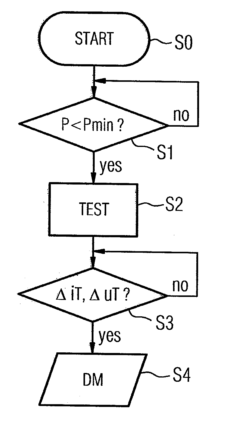
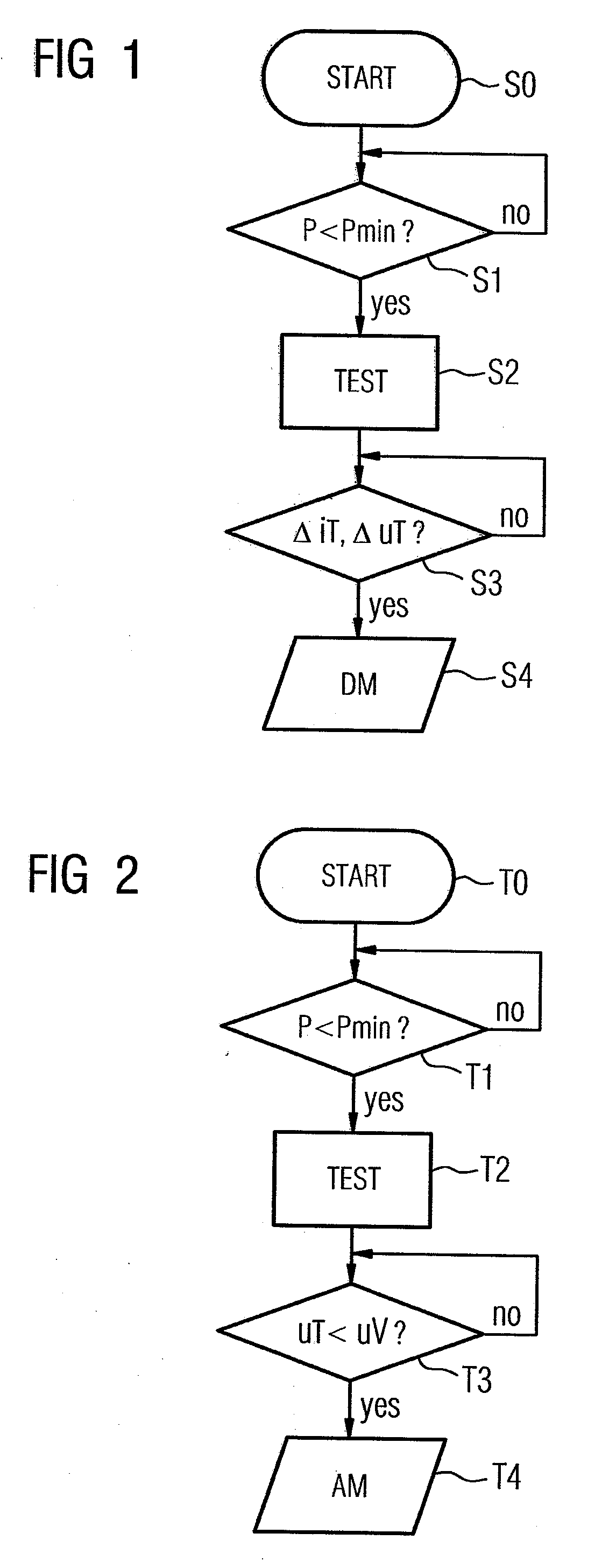
[0059]FIG. 1 is an illustration of a flowchart of a method for recognizing a theft. S0 designates a start step. A query is made in the following step S1 as to whether feeding operation is presently occurring in the PV system 100. To this end, a comparison is performed of the present electrical feed-in power P with a minimum feed-in power Pmin for which the operation of the power module of the PV inverter remains economical. If this is the case, a branch back to step S1 occurs. Otherwise, in step S2 denoted by “TEST”, i.e., during non-feeding operation i.e., in the evening and at night, a test voltage that is negative relative to the field voltage uT is connected to the at least one PV string line to set a test current iT through the bypass diodes. In the following step S3, a check is made to determine whether the test current iT changes significantly at a given test voltage uT or the test voltage uT changes significantly at a given test current iT. If no change is ascertained, a bra...


PUM


Abstract

A method for recognizing the theft of at least one photovoltaic module of a PV system. The PV system comprises at least one string of serially connected PV modules for supplying a field voltage, where the at least one string is connected in parallel and the PV modules each have a plurality of serially connected PV cells. In addition, bypass diodes connected in an anti-parallel manner are provided for protecting the PV cells. During a non-charging operation, i.e., the evening and at night, a test voltage that is negative relative to the field voltage is connected to the at least one PV string to adjust a test current through the bypass diodes. A theft message is automatically output when at least one of the test current and the test voltage significantly change.

Description

CROSS-REFERENCE TO RELATED APPLICATIONS[0001]This is a U.S. national stage of International Application No. PCT / EP2009 / 051559, filed on 11 Feb. 2009. Priority is claimed on German Application No. 10 2008 008 504.9, filed on 11 Feb. 2008. The entire content of both applications are incorporated herein by reference.BACKGROUND OF THE INVENTION[0002]1. Field of the Invention[0003]The invention relates to a method for recognizing a theft of at least one photovoltaic (PV) module of a PV system which has at least one string, connected in parallel, of serially connected PV modules for supplying a field voltage. Here, the PV modules have a plurality of serially connected PV cells.[0004]The invention furthermore relates to a method for recognizing a failure of at least one bypass diode of a PV module in a PV system which has at least one string, connected in parallel, of serially connected PV modules for supplying a field voltage, whereby the PV modules each have a plurality of serially conne...

Claims


Application Information

Patent Timeline
IPC IPC(8): G08B13/14
CPCH02S50/10G08B13/1409Y02E10/50
Inventor GIESLER, BODO
Owner SIEMENS AG
Learn More