Image correction apparatus and method and method of making transformation map for the same

Active Publication Date: 2011-02-10
NIPPON SOKEN +1
View PDF7 Cites 33 Cited by
  • Summary
  • Abstract
  • Description
  • Claims
  • Application Information

AI Technical Summary

Benefits of technology

[0013]In view of the above and other points, it is an objective of the present invention to provide an image correction apparatus and an image correction method that can provide easily-viewable image display even if an optical axis of an imaging de

Problems solved by technology

Hence, a three dimensional (3D) object is displayed on the vehicle right/left side image and the rear side image so that the displayed 3D object has discontinuity between the vehicle right/left side image and the rear side image, resulting in incomprehensible display.
Since a display

Method used


Image

  • Image correction apparatus and method and method of making transformation map for the same
  • Image correction apparatus and method and method of making transformation map for the same
  • Image correction apparatus and method and method of making transformation map for the same

Examples


Example

First Embodiment

[0039]A first embodiment will be described in detail with reference to the drawings.

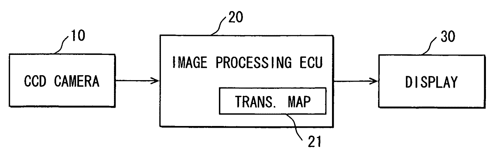
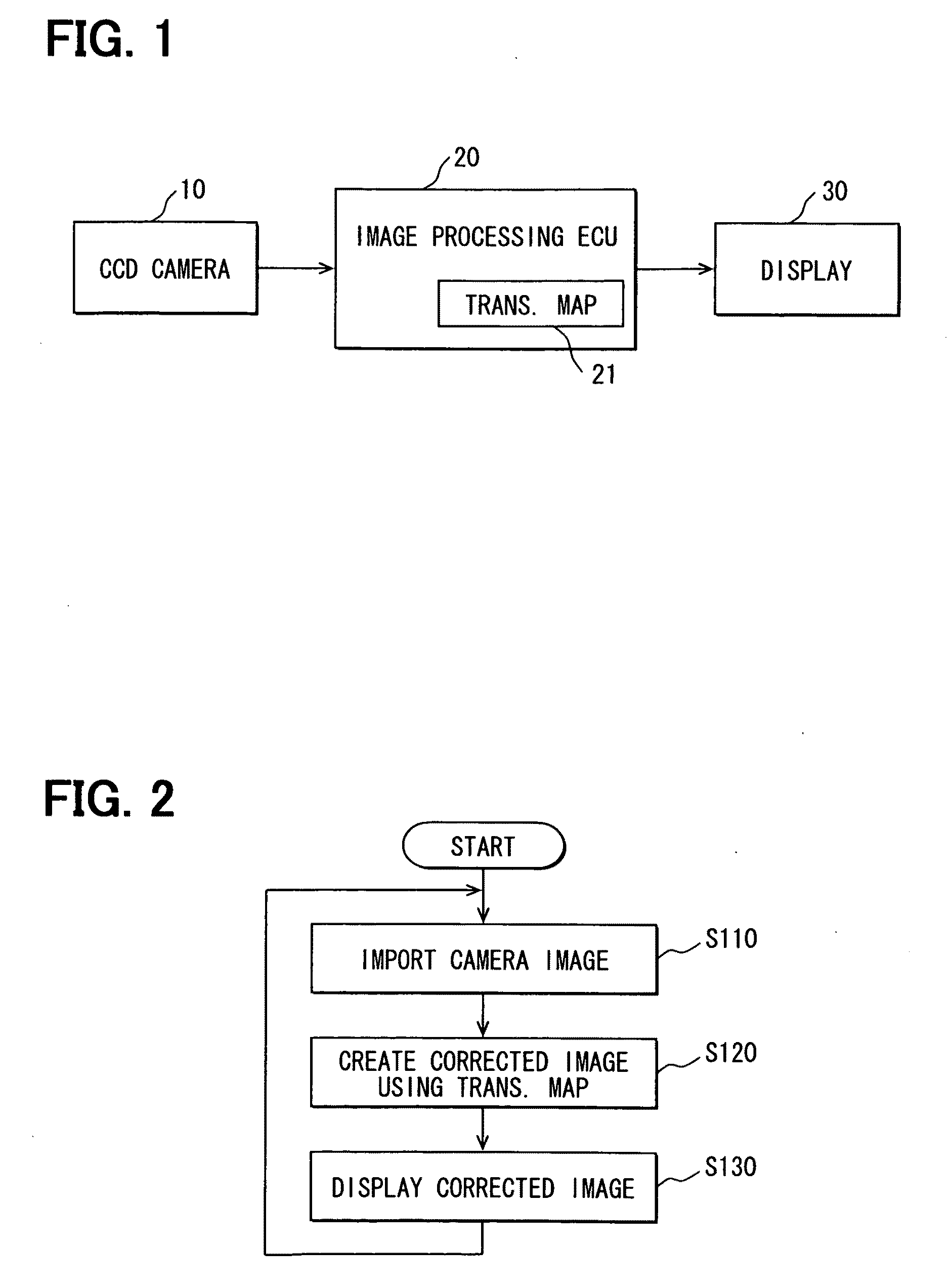
[0040]FIG. 1 is a block diagram illustrating an image correction apparatus of the first embodiment. In the present embodiment, explanation is given on the following example case. A CCD camera acting as an imaging device or means is mounted to a rear part of a vehicle to image a rear side of the vehicle. A correction is made on the image taken with the CCD camera.

[0041]As shown in FIG. 1, the image correction apparatus includes a CCD camera 10, an image processing electronic control unit (ECU) 20, and a display device 30.

[0042]The CCD camera 10 is mounted to a rear part of a vehicle. More specifically, the CCD camera 10 is mounted to a rear door or a trunk of the vehicle so that an optical axis of the CCD camera 10 is inclined downward with respect to a direction parallel to a ground surface. A field of view that the CCD camera 10 is to have in a rear side of the vehicle is predetermin...

Example

Second Embodiment

[0058]A second embodiment will be described. FIG. 6 is a block diagram illustrating an image creation apparatus of the second embodiment.

[0059]As shown in FIG. 6, a difference between the present embodiment and the first embodiment includes the followings. Multiple (e.g., three) CCD cameras 11 to 13 are mounted to a vehicle so that an optical axis of each CCD camera 11 to 13 points downward. An image created based on a combination of images captured by the multiple cameras 11 to 13 is displayed.

[0060]For illustrative purpose, the multiple CCD cameras 11 to 13 are assumed to be a first CCD camera 11, a second CCD camera 12, and a third CCD camera 13. The first CCD camera Ills mounted to a rear part of the vehicle to image a rear side of the vehicle, like the CCD camera 10 of the first embodiment is. The second CCD camera 12 is mounted in the vicinity of a left door mirror of the vehicle to image an area from a left side to a left-rear side of the vehicle. The third C...


PUM


Abstract

An image correction apparatus, an image correction method and a transformation map making method are disclosed. The apparatus includes an imaging device, a memory section, a corrected image creation section and a display device. The imaging device has an optical axis inclined upward or downward with respect to a ground surface, and captures an image. The corrected image creation section transforms the captured image into a corrected image in accordance with a transformation map stored in the memory section, thereby making a correction on inclination of a display object with respect to a vertical direction. The display device displays the corrected image.

Description

CROSS REFERENCE TO RELATED APPLICATION[0001]The present application is based on Japanese Patent Application No. 2009-183672 filed on Aug. 6, 2009, disclosure of which is incorporated herein by reference.BACKGROUND OF THE INVENTION[0002]1. Field of the Invention[0003]The present invention relates to an image correction apparatus and an image correction method adapted to correct an image provided from an imaging device, e.g., an imaging device mounted to a vehicle to image a periphery of the vehicle. The present invention also relates to a method of making a transformation map for the image correction apparatus and method.[0004]2. Description of Related Art[0005]A vehicle periphery displaying apparatus is known. For example, JP-H10-257482A discloses a vehicle periphery displaying apparatus that simultaneously displays images of a left side, a right side and a rear side of the vehicle on a liquid crystal display panel. This vehicle periphery displaying apparatus takes a vehicle right s...

Claims


Application Information

Patent Timeline
IPC IPC(8): H04N5/228
CPCB60R1/00B60R2300/105G06T1/00B60R2300/304B60R2300/607B60R2300/303
Inventor IMANISHI, MASAYUKIOOTSUKA, HIDEKI
Owner NIPPON SOKEN
Why Eureka
Try Eureka