Image display device

Inactive Publication Date: 2008-02-07
VISTA PEAK VENTURES LLC
View PDF1 Cites 18 Cited by
  • Summary
  • Abstract
  • Description
  • Claims
  • Application Information

AI Technical Summary

Benefits of technology

[0052] In still another preferred embodiment of the device according to the invention, the connecting conductive film is made of ITO. In this embodiment, since ITO has a comparatively high resistivity and a high corrosion resistance (i.e., less likely to corrode), ITO is appropriate to the material for the connecting conductive film. Moreover, by simply changing the mask pattern in the step of respectively forming the cap conductor films 127 and 128 on the surfaces of the mounting and testing electrodes 125 and 126 of the prior-art LCD device shown in FIGS. 1 and 2, an additional advantage that the structure or features of the invention can be easily realized is obtainable.
[0053] In a further preferred embodiment of the device according to the invention, an additional testing electrode is formed adjacent to t

Problems solved by technology

At this time, due to the low corrosion resist

Method used


Image

  • Image display device
  • Image display device
  • Image display device

Examples


first embodiment

[0066] An image display device according to a first embodiment of the present invention is shown in FIGS. 3 to 6, which is configured as a COG type LCD device 10.

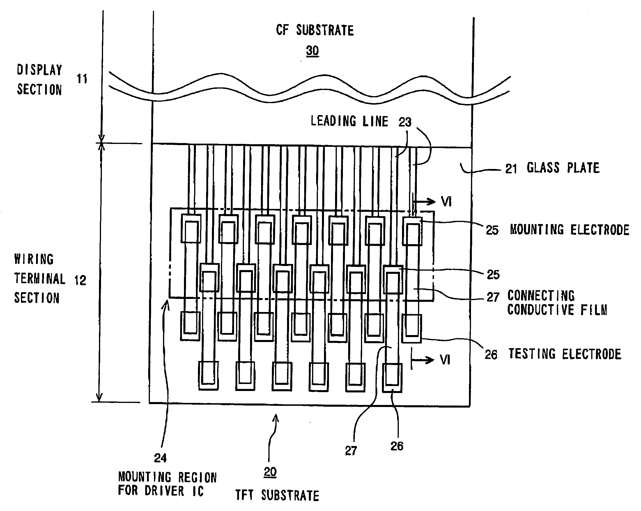
[0067] As shown in FIG. 3, the LCD device 10 according to the first embodiment comprises a display section 11 and a wiring terminal section 12 formed outside the display section 11 to be adjacent thereto. The display section 11 is a section or region for displaying images and includes a plurality of pixels arranged in a matrix array. The wiring terminal section 12 is a section or region in which a driver IC that drives the liquid crystal is mounted and a FPC is connected.

[0068] The schematic structures of the display section 11 and the wiring terminal section 12 are shown in FIG. 4. The display section 11 comprises a TFT substrate 20, a color filter (CF) substrate 30, and a liquid crystal 40 arranged between these two substrates 20 and 30. The TFT substrate 20 includes a glass plate 21, and TFTs and pixel electrodes (both...

second embodiment

[0093]FIG. 7 is an enlarged partial cross-sectional view similar to FIG. 6, which shows the schematic structure of the leading line 23 formed in the wiring terminal section 12 of a COG type LCD device as an image display device according to a second embodiment of the invention.

[0094] The leading line 23 in the second embodiment has the same structure as that of the leading line 23 in the above-described first embodiment except that three testing electrodes 26-1, 26-2, and 26-3 are provided instead of the testing electrode 26 for each of the mounting electrodes 25. It may be said that two additional testing electrodes 26-2 and 26-3 are added to the testing electrode 26-1 corresponding to the testing electrode 26 in the first embodiment. Therefore, the different portions from the first embodiment will be chiefly explained below.

[0095] As shown in FIG. 7, the leading line 23 comprises a patterned conductive film 23a with a narrow belt-like shape, three patterned conductive films 23b-...


PUM


Abstract

An image display device prevents display abnormality due to the corrosion and/or disappearance of the testing electrodes and/or and the conductive film for leading lines with a simple structure. Leading lines, which are in the wiring terminal section, electrically connect internal wiring lines to a driver IC. Each of the leading line has a mounting electrode and a testing electrode. A patterned first conductive film, which is separate from the testing electrode, connects electrically the mounting electrode to the corresponding internal wiring line in the display section. A patterned connecting conductive film is formed on an insulative film to contact with the mounting and testing electrodes, thereby making electrical interconnection between the mounting and testing electrodes. The connecting conductive film is made of a material (e.g., ITO) whose corrosion resistance is greater than a material (e.g., Cr) for the testing electrode.

Description

BACKGROUND OF THE INVENTION [0001] 1. Field of the Invention [0002] The present invention relates to an image display device such as a liquid-crystal display (LCD) device and a plasma display device. More particularly, the invention relates to an image display device having a display section including pixels arranged in a matrix array, and a wiring terminal section where a driver IC (Integrated Circuit) or driving semiconductor device is mounted. Mounting electrodes for mounting the driver IC and testing electrodes for testing the display section for defects are formed in the wiring terminal section. [0003] 2. Description of the Related Art [0004] In recent years, the LCD device has been extensively used as a high-resolution display or image display device. In general, the LCD device comprises a substrate (which will be referred to as the TFT substrate) on which switching elements such as thin-film transistors (TFTS) are formed, another substrate (which will be referred to as the CF...

Claims


Application Information

Patent Timeline
IPC IPC(8): G02F1/1345G02F1/01G02F1/1368G09F9/00G09F9/30
CPCG02F1/1345G02F2001/136254G02F1/1362G02F1/13458G02F1/136254
Inventor KOMAJU, MANABU
Owner VISTA PEAK VENTURES LLC
Why Eureka
Try Eureka