Optical Member, Method Of Manufacture Thereof, And Image Display Therewith

a technology of optical components and polarizing plates, which is applied in the field of optical components, can solve the problems of large amount of industrial waste generated, low area yield of polarizing plates, and complex and time-consuming, and achieves no reduction in production efficiency, easy inventory control, and high versatility.

Inactive Publication Date: 2007-09-13
NITTO DENKO CORP
View PDF1 Cites 16 Cited by
  • Summary
  • Abstract
  • Description
  • Claims
  • Application Information

AI Technical Summary

Benefits of technology

[0045] According to the invention, the optical film is processed into circular shape as stated above. Thus, optical members with high versatility can be produced without being affected by the optical film-specific optical axis, and optical members that allows easy inventory control can be provided with no reduction in production efficiency. The optical member of the invention also allows a fine tuning of its optical axis even after it is produced from the long size optical film. According to the invention, therefore, optical members with a high degree of flexibility in design and with high versatility can be provided. For the reason as stated above, cost reduction is also possible. Therefore, the use of such an optical member allows the production of lower-cost image displays.
[0046] Some sp

Problems solved by technology

Thus, the area yield of the polarizing plate is low, and there is a problem in which a large amount of industrial waste can be gene

Method used


Image

  • Optical Member, Method Of Manufacture Thereof, And Image Display Therewith
  • Optical Member, Method Of Manufacture Thereof, And Image Display Therewith

Examples


example 1

(Preparation of Polarizing Plate)

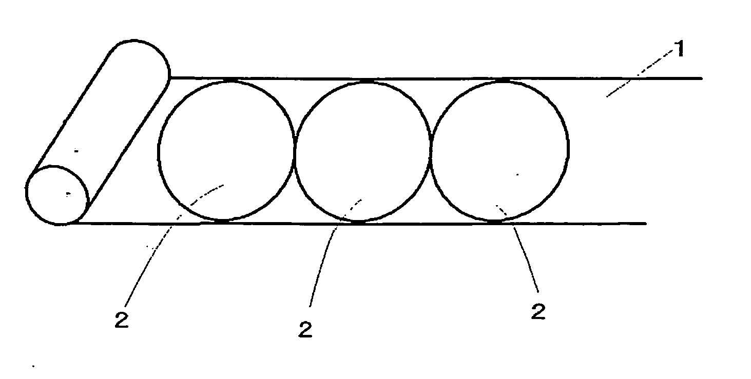
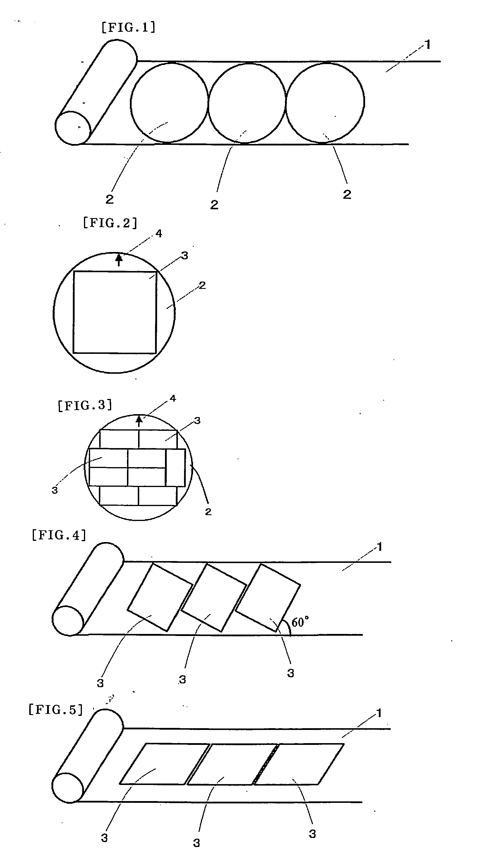
[0117] A long size polyvinyl alcohol (PVA) film was impregnated with iodine and stretched to form a polarizer with a width of 55 cm and a thickness of 30 μm. A polarizing plate was formed by bonding 80 μm-thick triacetylceliulose (TAC) films to both sides of the polarizer through a PVA adhesive layer with a post-drying thickness of about 1 μm. A release film made of a 25 μm-thick polyester (PE) film with its surface treated with a silicone release agent and an acrylic pressure-sensitive adhesive layer with a post-drying thickness of 20 μm was laminated on one side of the polarizing plate through the pressure-sensitive adhesive layer to prepare a polarizing plate. As shown in FIG. 1, 100 circular pieces were punched from the resulting polarizing plate with a perfect circle-shaped Thomson blade with a diameter of 480 mm.

(Preparation of Retardation Plate)

[0118] Similarly, a long size polycarbonate (PC) film was uniaxialiy stretched to form a long s...

example 2

[0120] Polarizing plates and retardation plates each with a diameter of 480 mm were prepared using the process of Example 1, and a circular shape optical member was prepared by laminating the polarizing plate and the retardation plate in such a manner that their optical axes made an angle of 40°.


PUM


Abstract

According to the invention, the optical film is processed into circular shape as stated above. Thus, optical members with high versatility can be produced without being affected by the optical film-specific optical axis, and optical members that allows easy inventory control can be provided with no reduction in production efficiency. And a method of processing a long size optical film into a circular shape, subsequently processing the optical film processed into the circular shape into an arbitrary shape, also allows a fine tuning of its optical axis even after it is produced from the long size optical film, therefore, optical members with a high degree of flexibility in design and with high versatility can be provided.

Description

TECHNICAL FIELD [0001] The invention relates to an optical member for use in image displays such as liquid crystal displays (LCDs), electroluminescence displays (ELDs), plasma displays (PDs), and field emission displays (FEDs), and to a method of producing the optical member. The invention also relates to an image display using the optical member. BACKGROUND ART [0002] A conventional method of producing a thin optical member for use in image displays, such as a polarizing plate and a retardation plate for use in liquid crystal displays, generally includes forming a pressure-sensitive adhesive layer or an adhesive layer on a long size optical member (optical film), attaching a release film or the like, and punching into a rectangular shape of the size and conditions that customers need from the optical member with the pressure-sensitive adhesive or adhesive layer protected by the release film or includes punching such shapes from the optical member itself without any pressure-sensiti...

Claims


Application Information

Patent Timeline
IPC IPC(8): G02B5/30B29D11/00
CPCG02B5/3083G02B5/305G02B5/30
Inventor IKEDA, HIDEOISHIZAKI, KOUJIITOU, MINORUKITADA, KAZUO
Owner NITTO DENKO CORP
Why Eureka
Try Eureka