

Method and circuit for driving electrophoretic display and electronic device using same
a technology of electrophoretic display and electronic device, applied in the direction of optics, static indicating device, instruments, etc., can solve the problems of poor viewing characteristics and prior art electrophoretic display, and achieve the effect of halting particle movement rapidly
- Summary
- Abstract
- Description
- Claims
- Application Information
AI Technical Summary
Benefits of technology
Problems solved by technology
Method used
Image

Examples
first embodiment
(1) First Embodiment
[0087] An electrophoretic display of the present embodiment displays an image according to an input image signal (VID). The display is capable of showing both static and animated images, but is particularly suited to showing static images.
[0088] (1-1) Outline of an Electrophoretic Display
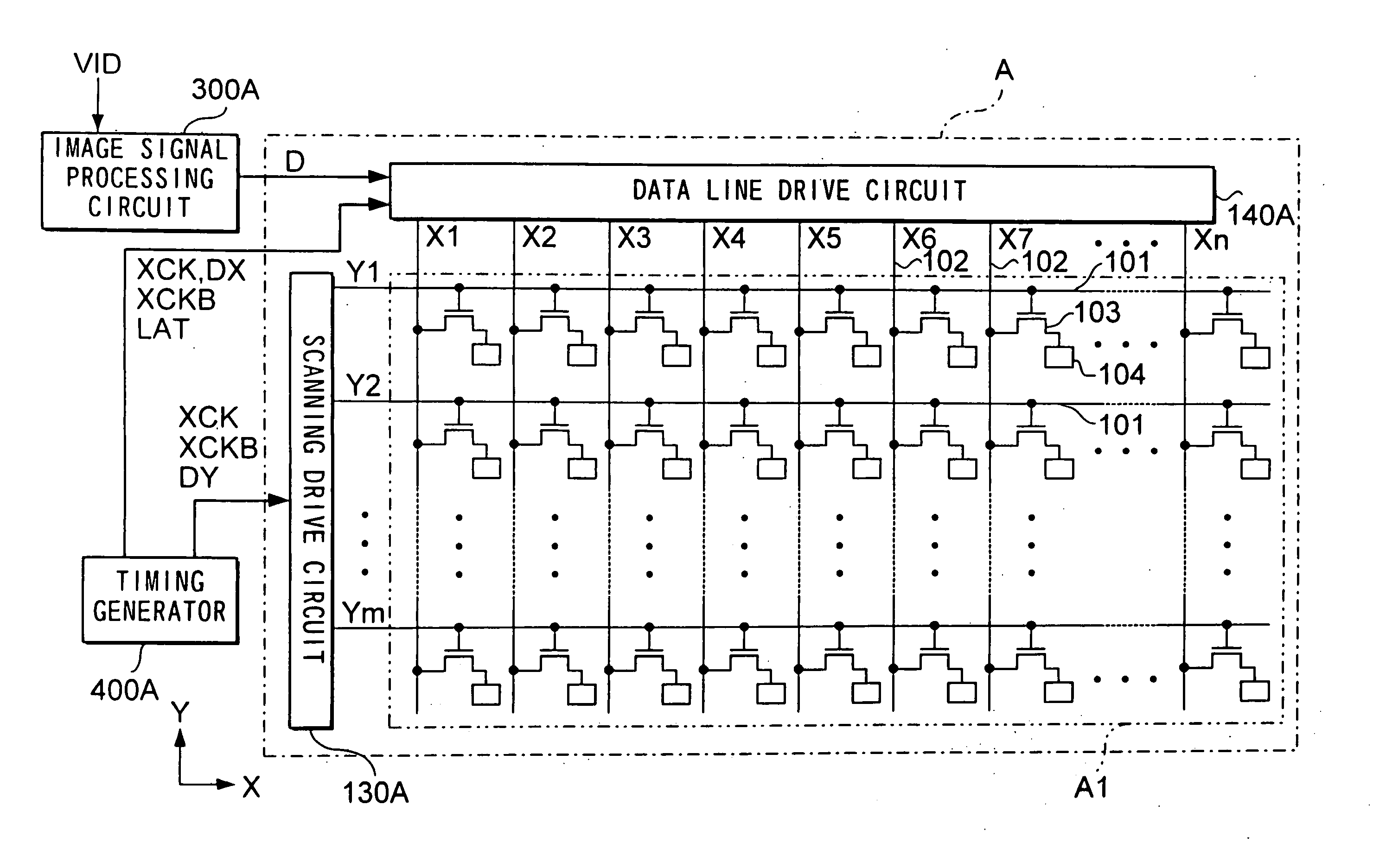
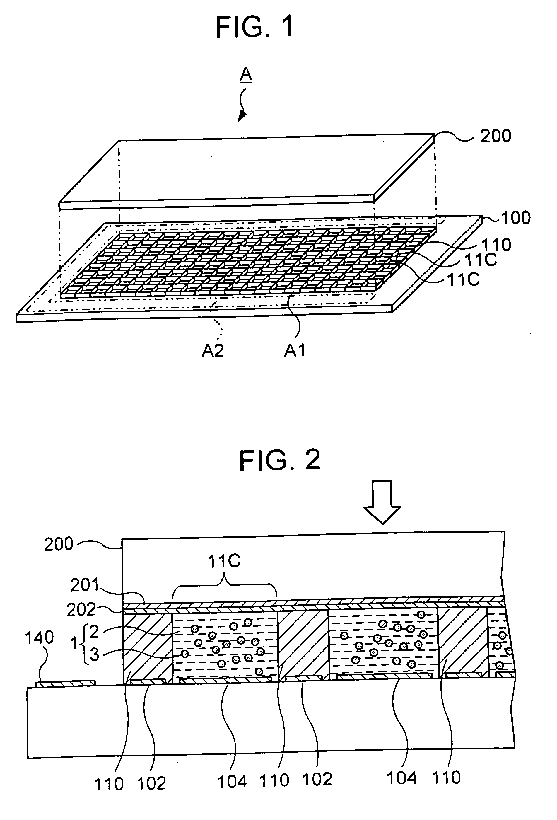
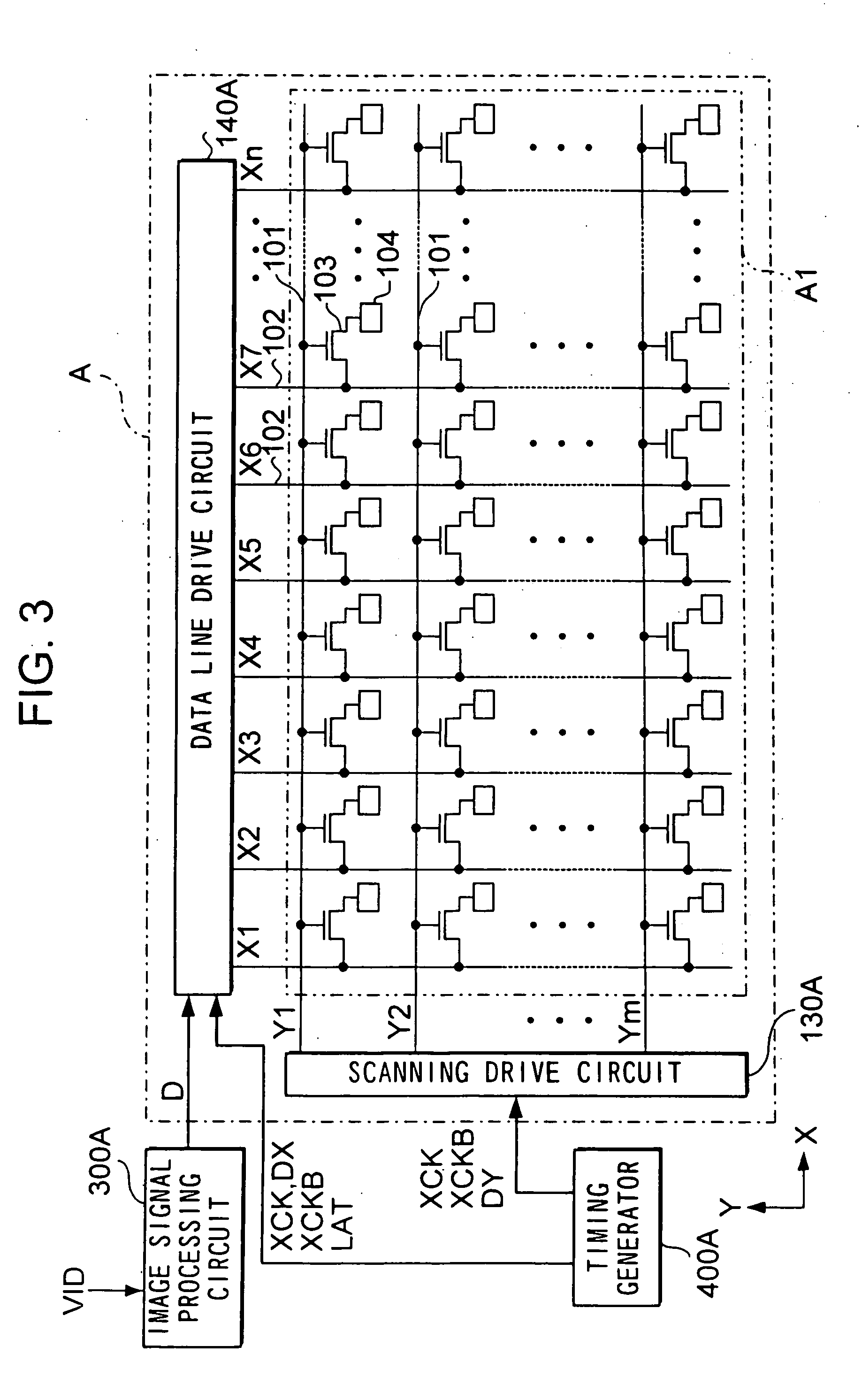
[0089] An electrophoretic display base on this embodiment has an electrophoretic display and peripheral drive circuits. FIG. 1 is an exploded perspective view showing the mechanical configuration of an electrophoretic display panel A, according to the first embodiment of the present invention. FIG. 2 is a partial sectional view of the panel.
[0090] As shown in FIGS. 1 and 2, an electrophoretic display panel A has an element substrate 100 and an opposing substrate 200. Element substrate 100 is made of glass, a semiconductor or some other suitable materials. A plurality of pixel electrodes 104 and bulkheads 110 are formed on the element substrate. Opposing substrate 200 is made o...
second embodiment
(2) Second Embodiment
[0160] (2-1) Outline of the Second Embodiment
[0161] In the above embodiment, rewriting is carried out in a way that after a reset operation as shown in the right diagram of FIG. 18 is carried out, then a writing operation is carried out shown in the middle diagram of FIG. 18 to update a displayed image. In this case, the position of the pigment particles 3 are initialized in displaying a subsequent image. In the case that dielectric fluid 2 is colored black and the pigment particles 3 are colored white, a black-out occurs across the entire image when an image is updated. Since the naked eye cannot recognize a rapid change in an image, if the change is effected sufficiently rapidly, an animation can be displayed by updating images continuously.
[0162] Nevertheless, there is a case that the resetting operation needs a long time according to physical property of the dispersal system 1, and a change in brightness in initializing the pigment particles 3 is therefore...
third embodiment
(3) Third Embodiment
[0189] In the first embodiment, firstly the applied voltage Va is applied to the pixel electrodes 104 during a time period corresponding to a color gradation to be displayed, to move the particles 3 by a distance corresponding to the gradation, secondly the common voltage Vcom is applied to the pixel electrodes 104 not to apply any electric field to the particles 3. Additionally, the image data D is compensated in the image signal processing circuit 300A before outputting, taking inertia into consideration, in a case that there is a low fluid resistance in the dielectric fluid 2, and the particles 3 are therefore able to continue to migrate under inertia.
[0190] In fact, it can take a considerable time for the pigment particles 3 to lose their kinetic energy depending on the level of fluid resistance encountered in the dielectric fluid 2. In the above example, since pigment particles 3 migrate away from pixel electrodes 104 to the common electrode, if there is li...
PUM
| Property | Measurement | Unit |
|---|---|---|
| specific gravity | aaaaa | aaaaa |
| specific gravity | aaaaa | aaaaa |
| thickness | aaaaa | aaaaa |
Abstract
Description
Claims
Application Information