Wavelength conversion laser light source and image display device

a laser light source and wavelength conversion technology, applied in the direction of laser details, instruments, light demodulation, etc., can solve the problems of difficult to raise the efficiency, limited interaction length l, and prominent drop in wavelength conversion efficiency, so as to suppress fluctuations in wavelength conversion efficiency of wavelength conversion elements and high wavelength conversion efficiency

Inactive Publication Date: 2011-02-10
PANASONIC CORP
View PDF6 Cites 10 Cited by
  • Summary
  • Abstract
  • Description
  • Claims
  • Application Information

AI Technical Summary

Benefits of technology

[0014]An object of this invention is to provide a high-output, high-stability wavelength conversion laser light source, the temperature tolerance width of the wavelength conversion element of which can be expanded in a state in which high wavelength conversion efficiency is maintained, and which can suppress fluctuations in the wavelength conversion efficiency of the wavelength conversion element due to unwanted fundamental waves.

Problems solved by technology

Moreover, wavelength conversion laser light sources are light sources used to obtain laser light at wavelengths difficult to obtain from direct oscillation of semiconductor laser diodes and solid state laser light sources.
However, if the interaction length L is made long, the conditions for making the phase difference Δk between the fundamental wave and the second harmonic small (for example, the fundamental wave incidence angle and wavelength conversion element temperature conditions) become more strict, so that the drop in wavelength conversion efficiency becomes prominent, and for practical purposes the interaction length L is limited.
For example, due to wavelength conversion element temperature conditions, the interaction length L has been limited, and it has been difficult to raise the efficiency.
However, in each of the above configurations proposed in the prior art, the wavelength conversion efficiency of a wavelength conversion laser light source can be improved, but there has been the problem that the wavelength conversion efficiency fluctuates greatly due to temperature changes of the wavelength conversion element.

Method used


Image

  • Wavelength conversion laser light source and image display device
  • Wavelength conversion laser light source and image display device
  • Wavelength conversion laser light source and image display device

Examples


embodiment 1

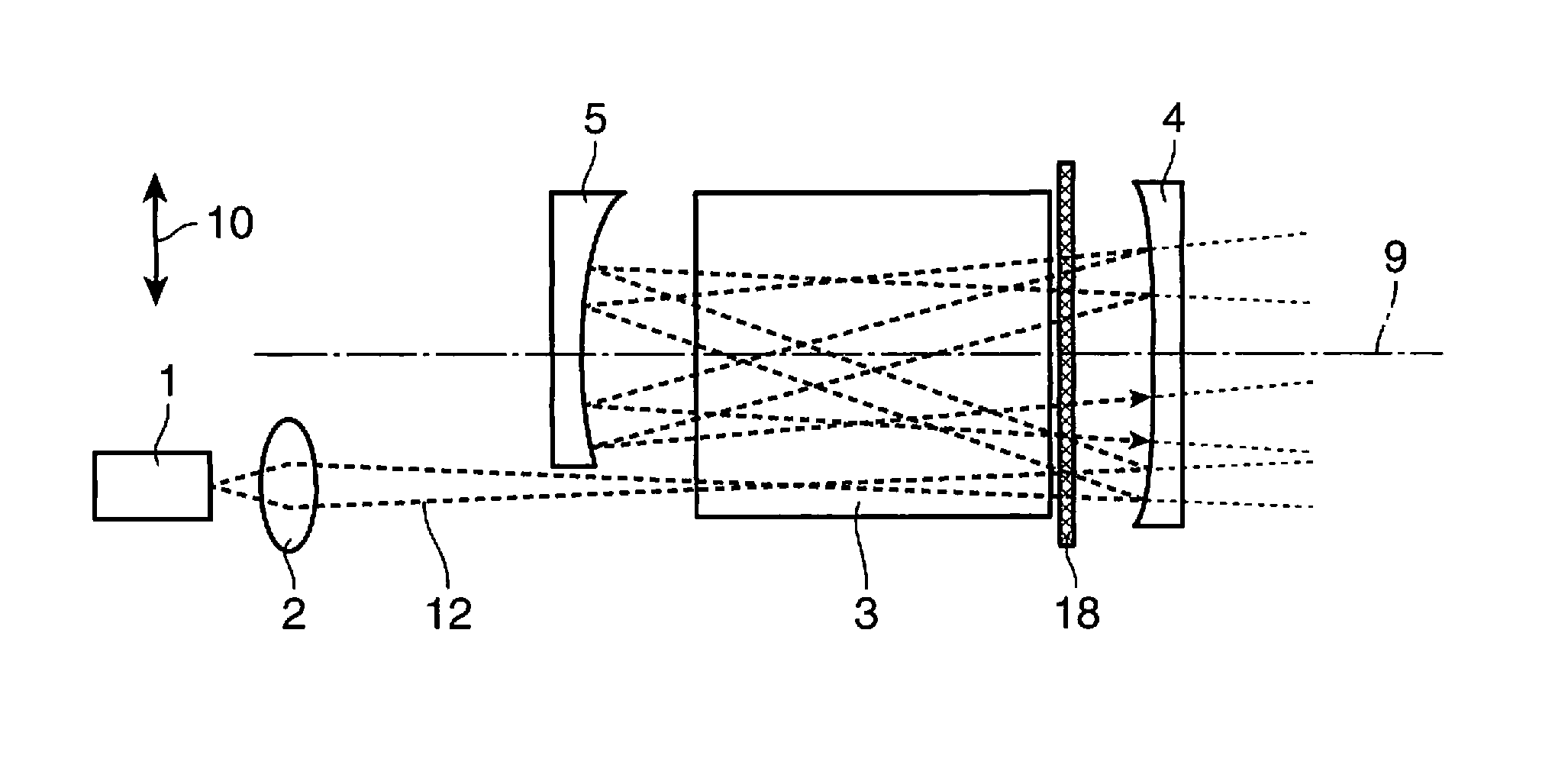
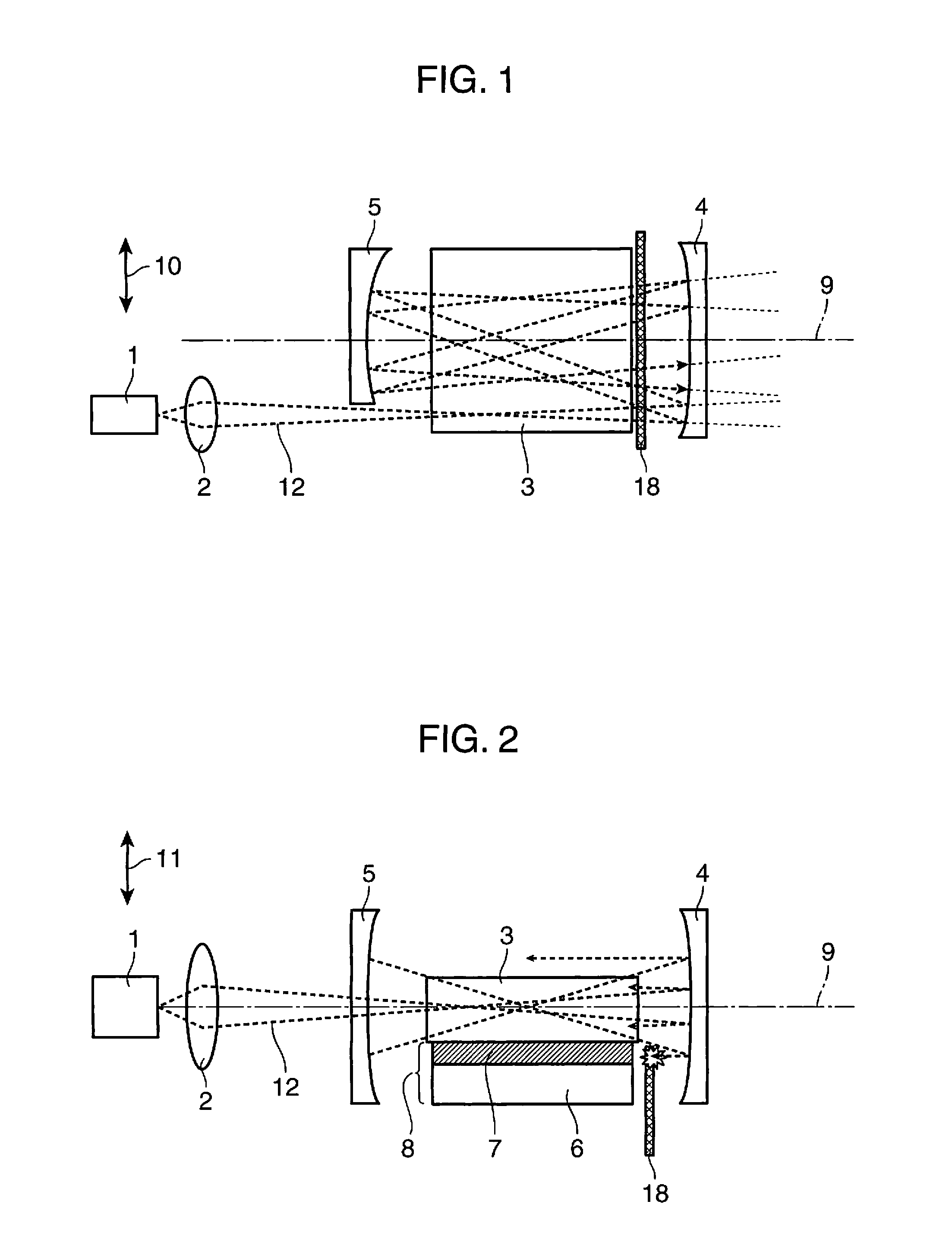
[0041]FIG. 1 and FIG. 2 show an example of the configuration of the wavelength conversion laser light source of Embodiment 1 of the invention; FIG. 1 is a top view of the wavelength conversion laser light source in this embodiment, and FIG. 2 is a side view of the configuration of the wavelength conversion laser light source shown in FIG. 1. Below, the directions indicated by the arrow 10 in FIG. 1 and by the arrow 11 in FIG. 2 are respectively taken to be the element width direction (the width direction of the wavelength conversion element 3) and the element thickness direction (the thickness direction of the wavelength conversion element 3).

[0042]In FIG. 1 and FIG. 2, reference numeral 1 denotes a fundamental wave laser light source to generate a fundamental wave, 2 denotes a condensing optical system to condense the fundamental wave, 3 denotes a wavelength conversion element to cause conversion of the fundamental wave into the second harmonic, 4 denotes a first concave mirror hav...

embodiment 2

[0101]FIG. 15 and FIG. 16 show an example of the configuration of the wavelength conversion laser light source of Embodiment 2 of the invention; FIG. 15 is diagram seen from above of the configuration of the wavelength conversion laser light source of this embodiment, and FIG. 16 is a diagram seen from the side of the configuration of the wavelength conversion laser light source shown in FIG. 15. Below, the directions indicated by the arrow 10 in FIG. 15 and by the arrow 11 in FIG. 16 are respectively taken to be the element width direction and the element thickness direction.

[0102]In FIG. 15 and FIG. 16, reference numeral 1 denotes a fundamental wave laser light source to generate a fundamental wave, 2 denotes a condensing optical system to condense the fundamental wave, 3 denotes a wavelength conversion element to cause conversion of the fundamental wave into the second harmonic, 4 denotes a first concave mirror having curvature R1, 5 denotes a second concave mirror having curvatu...

embodiment 3

[0114]FIG. 17 and FIG. 18 schematically show an example of the configuration of the wavelength conversion laser light source of Embodiment 3 of the invention; FIG. 17 is diagram seen from above of the wavelength conversion laser light source of this embodiment, and FIG. 18 is a diagram seen from the side of the wavelength conversion laser light source shown in FIG. 17. Below, the directions indicated by the arrow 10 in FIG. 17 and by the arrow 11 in FIG. 18 are respectively taken to be the element width direction and the element thickness direction.

[0115]In FIG. 17 and FIG. 18, reference numeral 1 denotes a fundamental wave laser light source to generate a fundamental wave, 2 denotes a condensing optical system to condense the fundamental wave, 3 denotes a wavelength conversion element to cause conversion of the fundamental wave into the second harmonic, 74 denotes a first concave mirror having curvature R1, 5 denotes a second concave mirror having curvature R2 different from curvat...


PUM

PropertyMeasurementUnit
focal length f2aaaaaaaaaa

Abstract

A wavelength conversion laser light source includes a fundamental wave laser light source (1) to generate a fundamental wave; a first mirror and a second mirror (4, 5), arranged so as to oppose each other; a wavelength conversion element (3) which is arranged between the first mirror and the second mirror and converts the wavelength of the fundamental wave; and a temperature control portion (8) to control the temperature of the wavelength conversion element. A portion of the fundamental wave is wavelength-converted in the wavelength conversion element, and moreover the fundamental wave which is not wavelength-converted is reflected by the first mirror and the second mirror and is repeatedly incident on the wavelength conversion element and is wavelength-converted, and the temperature control portion is arranged so as to be in contact with the wavelength conversion element, and the light quantity of the fundamental wave incident on the temperature control portion is reduced by a fundamental wave absorption portion (18).

Description

TECHNICAL FIELD[0001]This invention relates to a wavelength conversion laser light source which converts the wavelength of fundamental laser light, and an image display device using the same.BACKGROUND ART[0002]Laser light sources widely used in industrial applications and as devices incorporated into consumer equipment include semiconductor laser diodes and solid state laser light sources and similar. Moreover, wavelength conversion laser light sources are light sources used to obtain laser light at wavelengths difficult to obtain from direct oscillation of semiconductor laser diodes and solid state laser light sources.[0003]In a wavelength conversion laser light source, the laser light frequency, that is, the wavelength, is converted through nonlinear optical effects such as SHG (Second Harmonic Generation), in which light at twice the frequency (the second harmonic) of the fundamental wave laser light (hereafter abbreviated to fundamental wave) incident on a wavelength conversion...

Claims


Application Information

Patent Timeline
Patent Type & Authority Applications(United States)
IPC IPC(8): G02F1/35
CPCG02F1/3501G02F2001/3542G02F2203/60G02F2201/17G02F2203/12G02F2001/3548G02F1/3542G02F1/3548
Inventor HORIKAWA, NOBUYUKIFURUYA, HIROYUKIMIZUSHIMA, TETSUROKUSUKAMA, KOICHISUGITA, TOMOYAYAMAMOTO, KAZUHISA
Owner PANASONIC CORP
Why Eureka
Try Eureka