

Multilayer capacitor array mounting structure
a multi-layer capacitor and mounting structure technology, applied in the direction of capacitors, fixed capacitors, electrical appliances, etc., can solve the problems of power consumption, noise that is known to occur in power, and noise that is not provided with a mounting structure for eliminating these two noises, so as to achieve the effect of eliminating two noises
- Summary
- Abstract
- Description
- Claims
- Application Information
AI Technical Summary
Benefits of technology
Problems solved by technology
Method used
Image

Examples
first embodiment
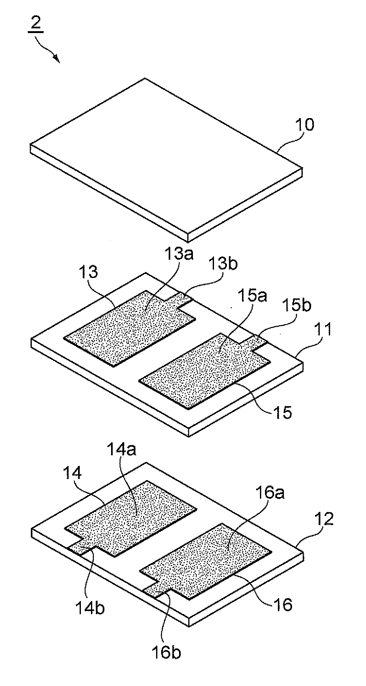
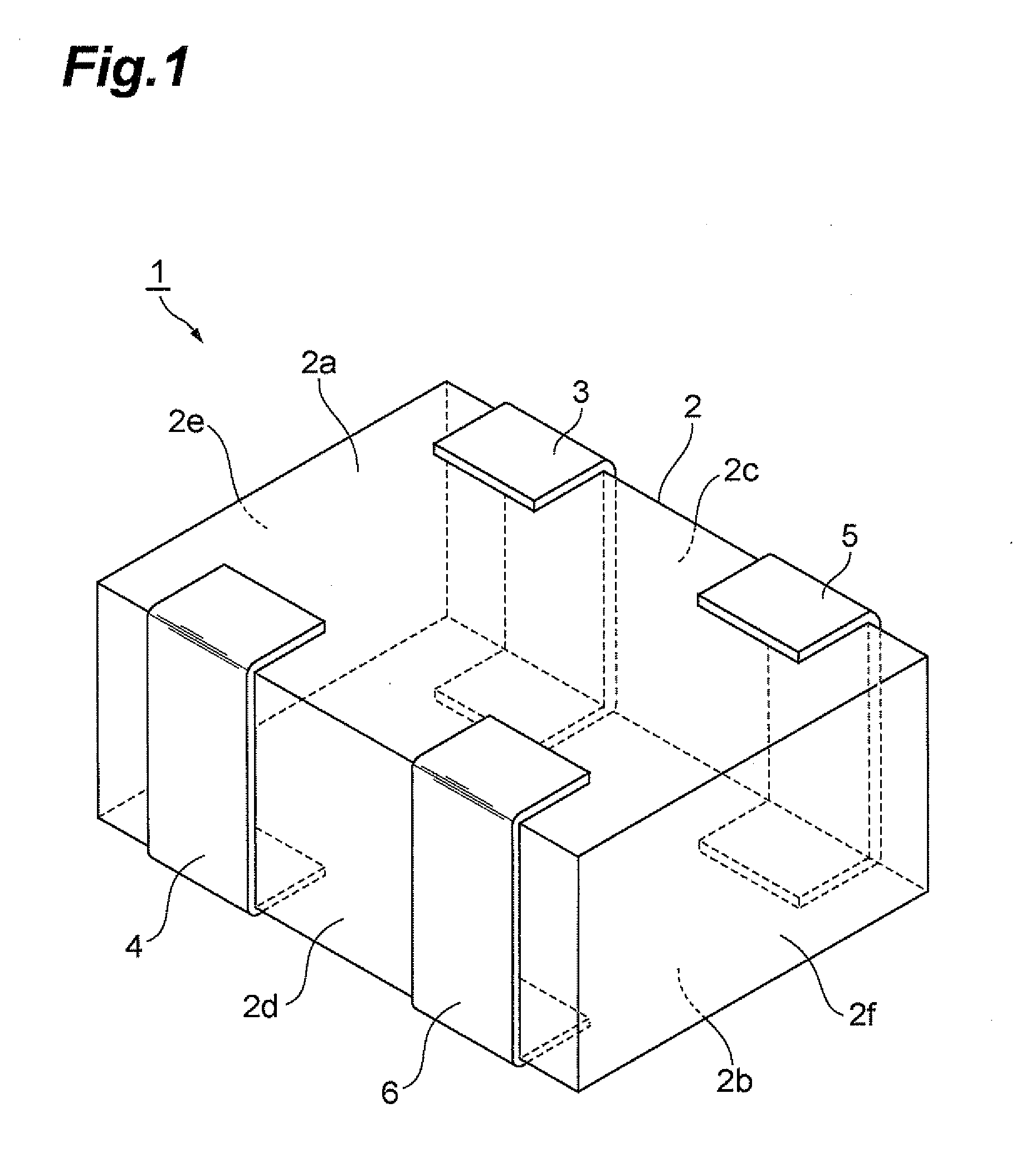
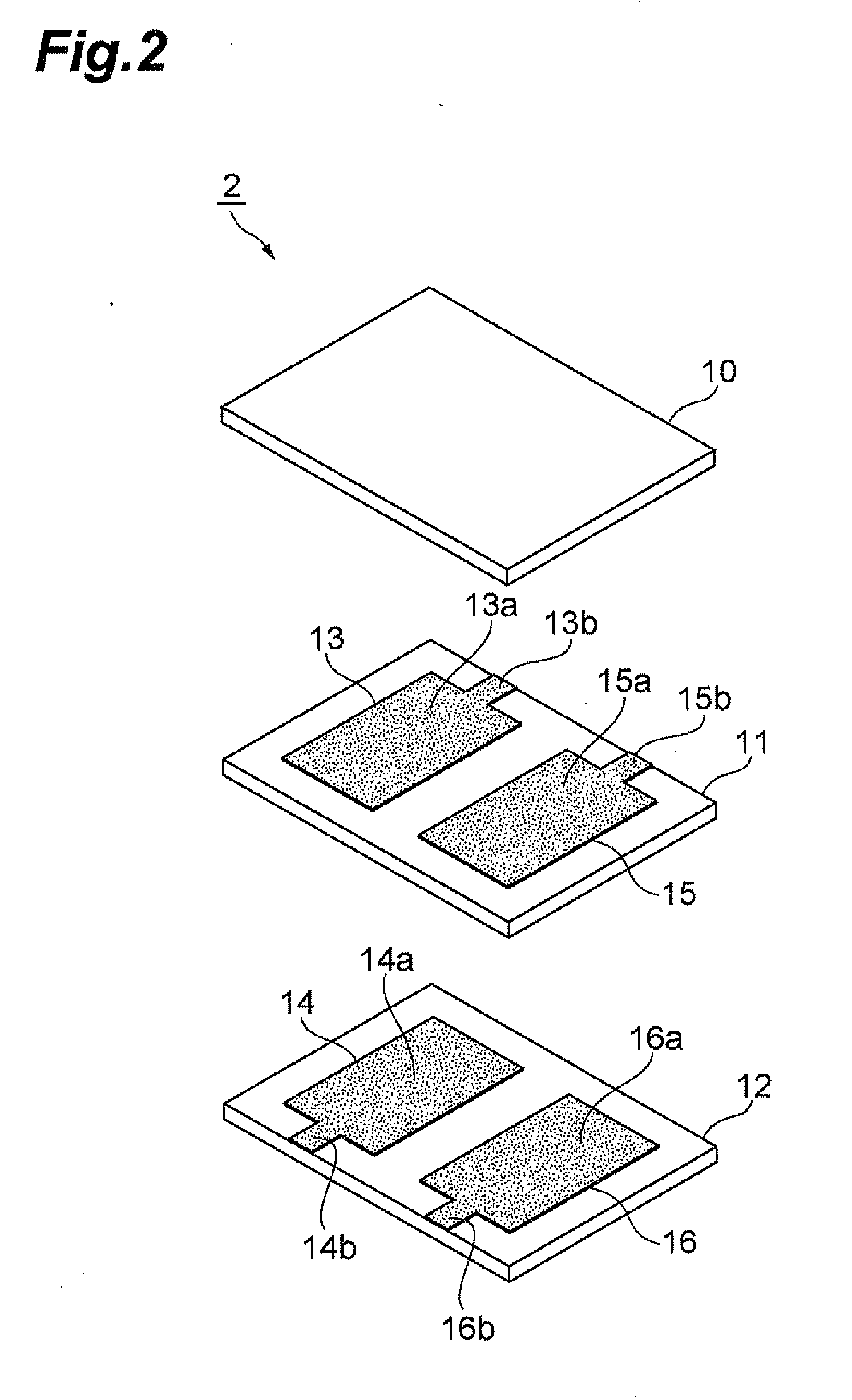
[0039]To begin with, a multilayer capacitor array 1 in accordance with the first embodiment will be explained with reference to FIGS. 1 and 2. As illustrated in FIG. 1, the multilayer capacitor array 1 is a double capacitor array comprising a capacitor element body 2 having a rectangular parallelepiped form and terminal electrodes 3, 4, 5, 6 disposed on the outer surface of the capacitor element body 2. The capacitor element body 2 includes first and second main faces 2a, 2b opposing each other; first and second side faces 2c, 2d opposing each other and extending along longer-side directions of the first and second main faces 2a, 2b; and third and fourth side faces 2e, 2f opposing each other and extending along shorter-side directions of the first and second main faces 2a, 2b. The first and second side faces 2c, 2d and third and fourth side faces 2e, 2f extend such as to connect the first and second main faces 2a, 2b to each other.
[0040]The first and third terminal electrodes 3, 5 a...
second embodiment
[0055]The structure of a multilayer capacitor array 31 in accordance with the second embodiment will now be explained with reference to FIGS. 7 and 8. As illustrated in FIG. 7, the multilayer capacitor array 31 is a quadruple capacitor array comprising a capacitor element body 32 having a rectangular parallelepiped form and terminal electrodes 3, 4, 5, 6, 33, 34, 35, 36 disposed on the outer surface of the capacitor element body 32. As with the capacitor element body 2, the capacitor element body 32 includes first and second main faces 32a, 32b, first and second side faces 32c, 32d, and third and fourth side faces 32e, 32f.
[0056]In addition to the first and third terminal electrodes 3, 5, the fifth and seventh terminal electrodes 33, 35 are disposed on the first side face 32c of the capacitor element body 32. The first, third, fifth, and seventh terminal electrodes 3, 5, 33, 35 are located in the order of the fifth terminal electrode 33, first terminal electrode 3, third terminal e...
third embodiment
[0073]The structure of a multilayer capacitor array 71 in accordance with the third embodiment will now be explained with reference to FIGS. 17 and 18. As illustrated in FIG. 17, the multilayer capacitor array 71 is a double capacitor array comprising a capacitor element body 72 having a rectangular parallelepiped form and terminal electrodes 73, 74, 75, 76 disposed on the outer surface of the capacitor element body 72. As with the capacitor element body 2, the capacitor element body 72 includes first and second main faces 72a, 72b; first and second side faces 72c, 72d; and third and fourth side faces 72e, 72f.
[0074]The first and second terminal electrodes 73, 74 are disposed on the second side face 72d of the capacitor element body 72. The first and second terminal electrodes 73, 74 are located in this order in the direction from the third side face 72e to the fourth side face 72f. The third and fourth terminal electrodes 75, 76 are formed on the first side face 72c of the capacit...
PUM
 Abstract
Description
Claims
Application Information