Systems and methods for mitigating interference between access points

a technology of access points and interference, applied in the field of communication, can solve the problems of difficult and expensive deployment of access points, relatively few physical locations may actually be available, and many landowners do not have leases or easements, etc., to facilitate the use of tdd techniques, and reduce the number of base site locations

Inactive Publication Date: 2011-02-10
FIMAX TECH
View PDF6 Cites 88 Cited by
  • Summary
  • Abstract
  • Description
  • Claims
  • Application Information

AI Technical Summary

Benefits of technology

[0010]The cooperative antenna beam control techniques of the present invention are particularly well suited for use with respect to TDD communications. Specifically, even where network nodes are disposed in close proximity, such that transmissions in the same frequency band by different nodes would otherwise result in substantial interference, embodiments of the present invention facilitate use of TDD techniques and dense reuse of FDMA channels.
[0011]Embodiments of the invention minimize the number of base site locations, thus lowering the total cost of deployment. Through application of the concepts of the present invention a plurality of access points can be put at close proximity in one base site where interference can be mitigated and the total cost of deployment can be lowered.

Problems solved by technology

It is often difficult and expensive to deploy a network of access points in order to provide wireless communication infrastructure to serve a large area.
Such leases or easements are not available from many landowners, such as due to the perceived aesthetic impact which may be associated with the deployment of an access point, and are often quite expensive.
Therefore, a relatively few physical locations may actually be available for deployment of access points.
Moreover, deployment of access points often requires attendant infrastructure, such as towers or other elevated structure for the deployment of antenna systems, fiber optic or other high bandwidth data links for backhaul of data, physical shelter to house transceiver equipment, electric mains to provide necessary power, etc.
All this attendant infrastructure adds to the cost and the complexity of deploying access points to provide widespread coverage of a service area.
Communication systems, particularly wireless communication systems, are susceptible to interference, whether in the form of external noise or interfering signals from various stations of the communication systems themselves.
Although such FDD techniques provide a level of interference mitigation, such techniques require appreciable amounts of spectrum.
Such spectrum is often not readily available, such as due to spectrum licensing and / or the available bandwidth of unlicensed frequencies.
Accordingly, FDD techniques are not available or practical with respect to some communication system implementations.
However, in a network system, wherein a plurality of remote terminals are in communication with different access points, transmission by one such node may block reception of other transmissions by another such node.
Where the particular nodes are disposed in relatively close proximity, or otherwise have a relatively clear line of sight, such TDD transmissions may block or otherwise substantially interfere with reception of a different channel (e.g., a different frequency channel in a frequency division multiple access (FDMA) TDD system) due to the relative signal levels, the relative proximities, the close spacing of the channels, etc.
Accordingly, although providing spectrum efficiencies, systems implementing TDD techniques may suffer from substantial interference as a result of network communications.
As with the aforementioned FDD, such channel reuse schemes do not use the spectrum efficiently.

Method used


Image

  • Systems and methods for mitigating interference between access points
  • Systems and methods for mitigating interference between access points
  • Systems and methods for mitigating interference between access points

Examples


Embodiment Construction

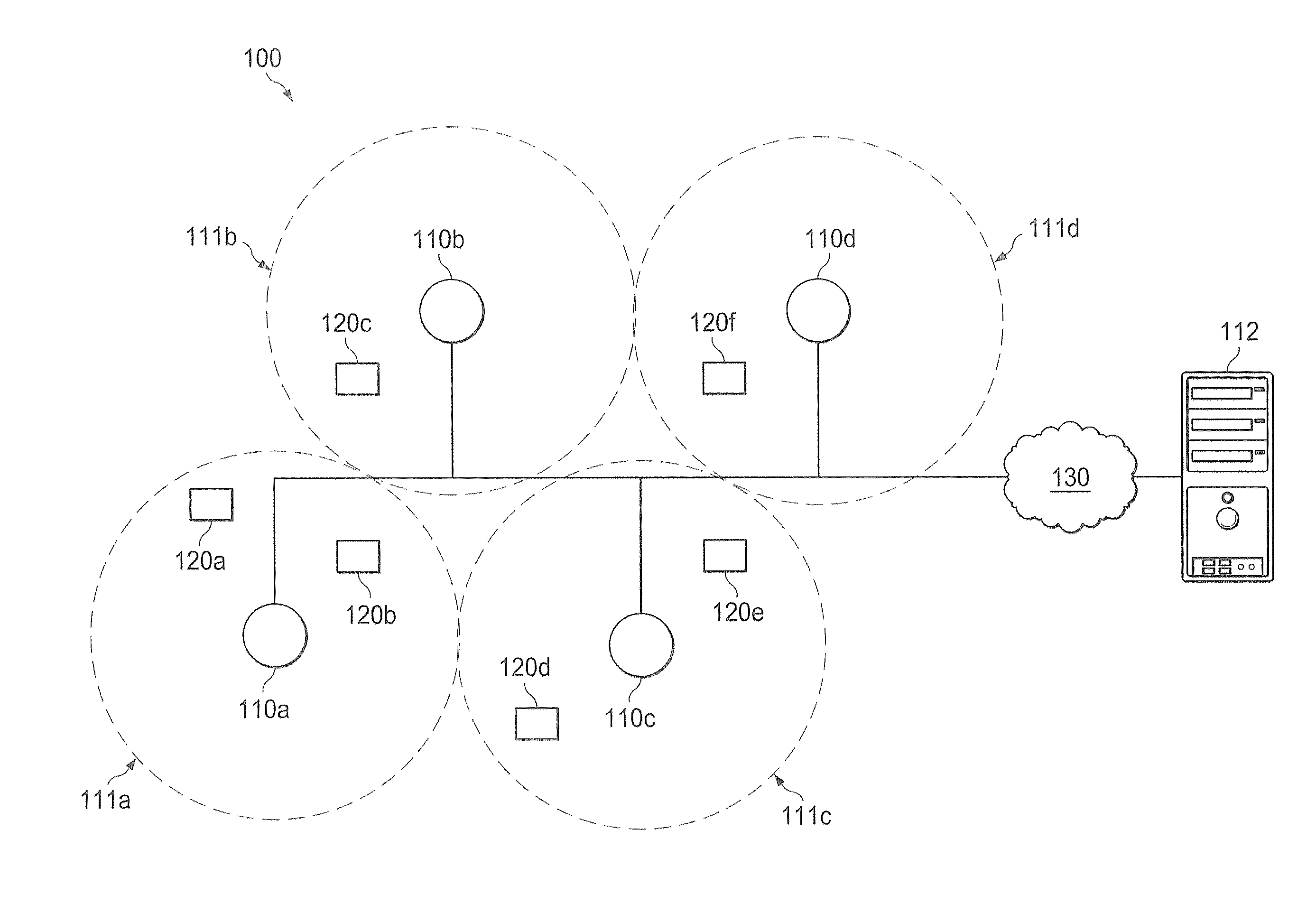
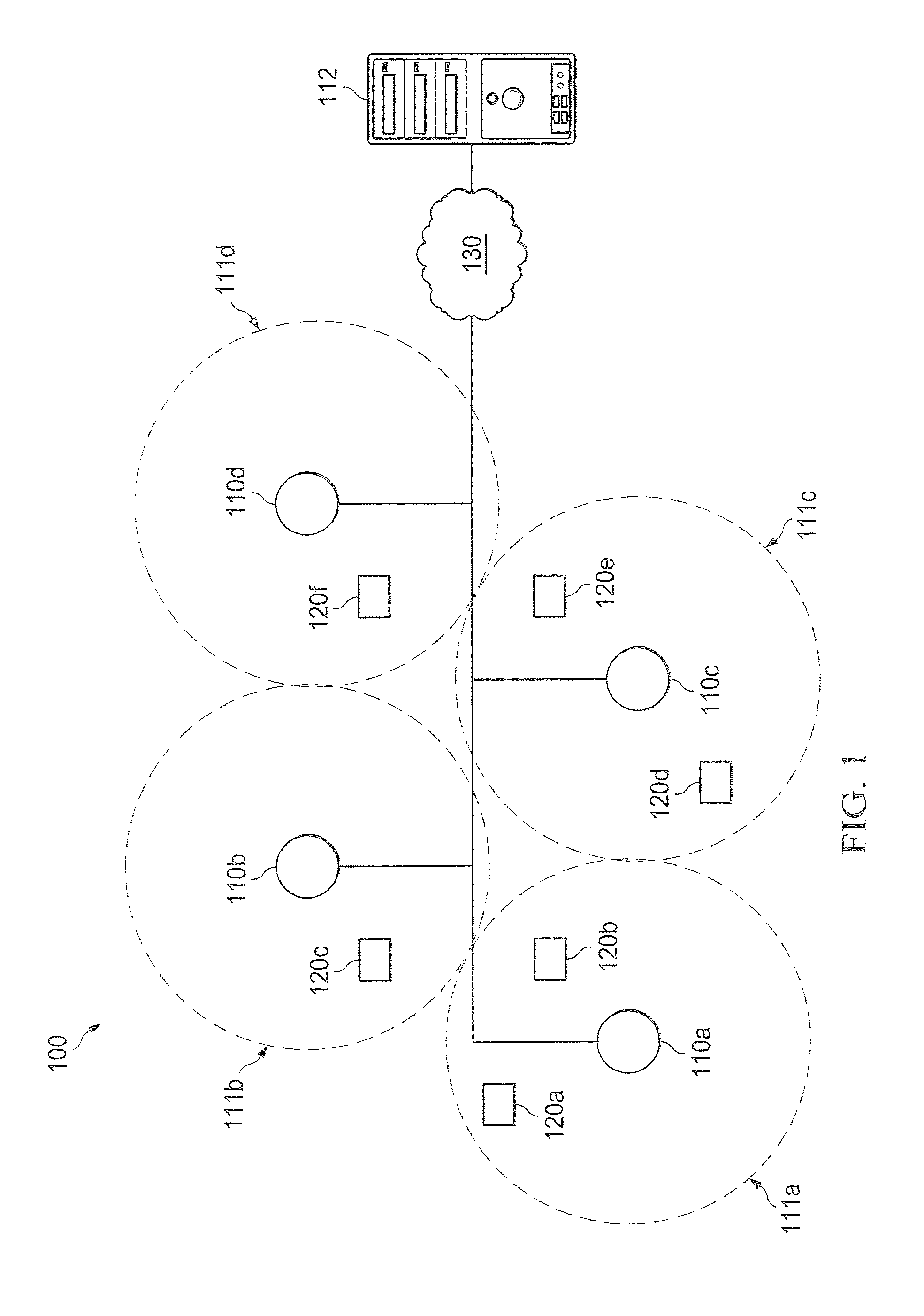
[0025]FIG. 1 shows a wireless communication system adapted according to embodiments of the present invention. Specifically, wireless communication system 100 is shown comprising base sites 110a-110d, each having a service area associated therewith (shown as service areas 111a-111d, respectively), and terminals 120a-120f. Each of base sites 110a-110d and terminals 120a-120f are wireless nodes of wireless communication system 100, wherein such wireless nodes may communicate wirelessly with one another. For example, bidirectional links may be provided between a base site of base sites 110a-110d and an associated terminal of terminals 120a-120f to provide broadband communication therebetween. Base sites 110a-110d may, for example, be coupled to various other systems, networks, etc., such as through network 130, to facilitate communication between such systems and networks and terminals 120a-120f. Accordingly, wireless communication system 100 of the illustrated embodiment provides a cel...


PUM


Abstract

Systems and methods which implement cooperative techniques at wireless network access points to provide interference mitigation are shown. Embodiments utilize cooperative antenna beam adaptation techniques wherein antenna beam selection, selective antenna beam transmission power, and/or antenna beam null selection is implemented based upon the communication environment created by a plurality of access points. Additionally or alternatively, embodiments utilize cooperative antenna beam isolation techniques wherein narrow channel filters are implemented with respect to antenna beam signals and/or shielding is provided between various antenna beams based upon the communication environment created by a plurality of access points. Embodiments additionally or alternatively utilize cooperative antenna beam coordination techniques wherein transmission and/or reception of signals is coordinated, the use of antenna beams is coordinated, and/or interference cancellation is implemented based upon the communication environment created by a plurality of access points.

Description

CROSS-REFERENCE TO RELATED APPLICATIONS[0001]The present application is related to co-pending and commonly assigned U.S. patent applications Ser. No. 11 / 842,864 entitled “Adaptive Interference Control,” filed Aug. 21, 2007, Ser. No. 11 / 770,559 entitled “Systems and Methods Using Antenna Beam Scanning for Improved Communications,” filed Jun. 28, 2007, and Ser. No. 12 / 470,537 entitled “Multi-Function Wireless Systems and Methods,” filed May 22, 2009, the disclosures of which are hereby incorporated herein by reference.TECHNICAL FIELD[0002]The invention relates generally to communications and, more particularly, to mitigating interference between access points, such as where multiple access points are in close proximity or are otherwise disposed to experience interference.BACKGROUND OF THE INVENTION[0003]Communication infrastructure has become nearly ubiquitous in developed parts of the world. Both wireline and wireless communication systems are pervasively deployed throughout populous...

Claims


Application Information

Patent Timeline
Patent Type & Authority Applications(United States)
IPC IPC(8): H04B15/00H04W4/00H04J3/00
CPCH04B7/0434H04W16/28H04B7/0617H04B7/0495
Inventor YEUNG, SIMONCHAN, BENLEUNG, JASONGEORGE, DOUGWONG, PIU BILL
Owner FIMAX TECH
Why Eureka
Try Eureka