Network system, packet forwarding apparatus, and method of forwarding packets

a packet forwarding and packet technology, applied in the field of packet forwarding, can solve the problems of terminals not being able to access the authentication network, communication in layer b>3/b> cannot be completed prior to authentication, and the utilization efficiency of ip address is low, so as to achieve the effect of improving the utilization efficiency of ip address

Inactive Publication Date: 2011-02-10
ALAXALA NETWORKS
View PDF22 Cites 83 Cited by
  • Summary
  • Abstract
  • Description
  • Claims
  • Application Information

AI Technical Summary

Benefits of technology

[0072]In the method of forwarding packets of this application, prior to determination of successful authentication for a terminal by the authentication server, a first forwarding route table that includes packet routing information to a prescribed device connected to the second network is employed for packets sent from the terminal, and thus packet forwarding of packets from the terminal to the second network (authentication server) is allowed, while forwarding to the third network is prevented. After determination of successful authentication, a second forwarding routing information group that includes packet routing informati

Problems solved by technology

However, a problem with dynamic VLAN systems is that different IP addresses are assigned to the same terminal before and after authentication, so IP address utilization efficiency is low.
A problem with static VLAN systems is that communication in Layer 3 is not possible prior to authentication.
One problem with the above technique of isolating the authentication network and the enterprise network through VPNs is that subsequent to authentication, the terminal can no longer access the authentication network.
This creates the problem that the server belonging to the authentication network (the authentication server) cannot be used, for example, to carry out periodic quarantines (e.g. that the virus definition file is the most recent or that the operating system is the latest version) for the authenticated terminal.
This problem is not limit

Method used


Image

  • Network system, packet forwarding apparatus, and method of forwarding packets
  • Network system, packet forwarding apparatus, and method of forwarding packets
  • Network system, packet forwarding apparatus, and method of forwarding packets

Examples


embodiment 1

A. Embodiment 1

A1. System Configuration

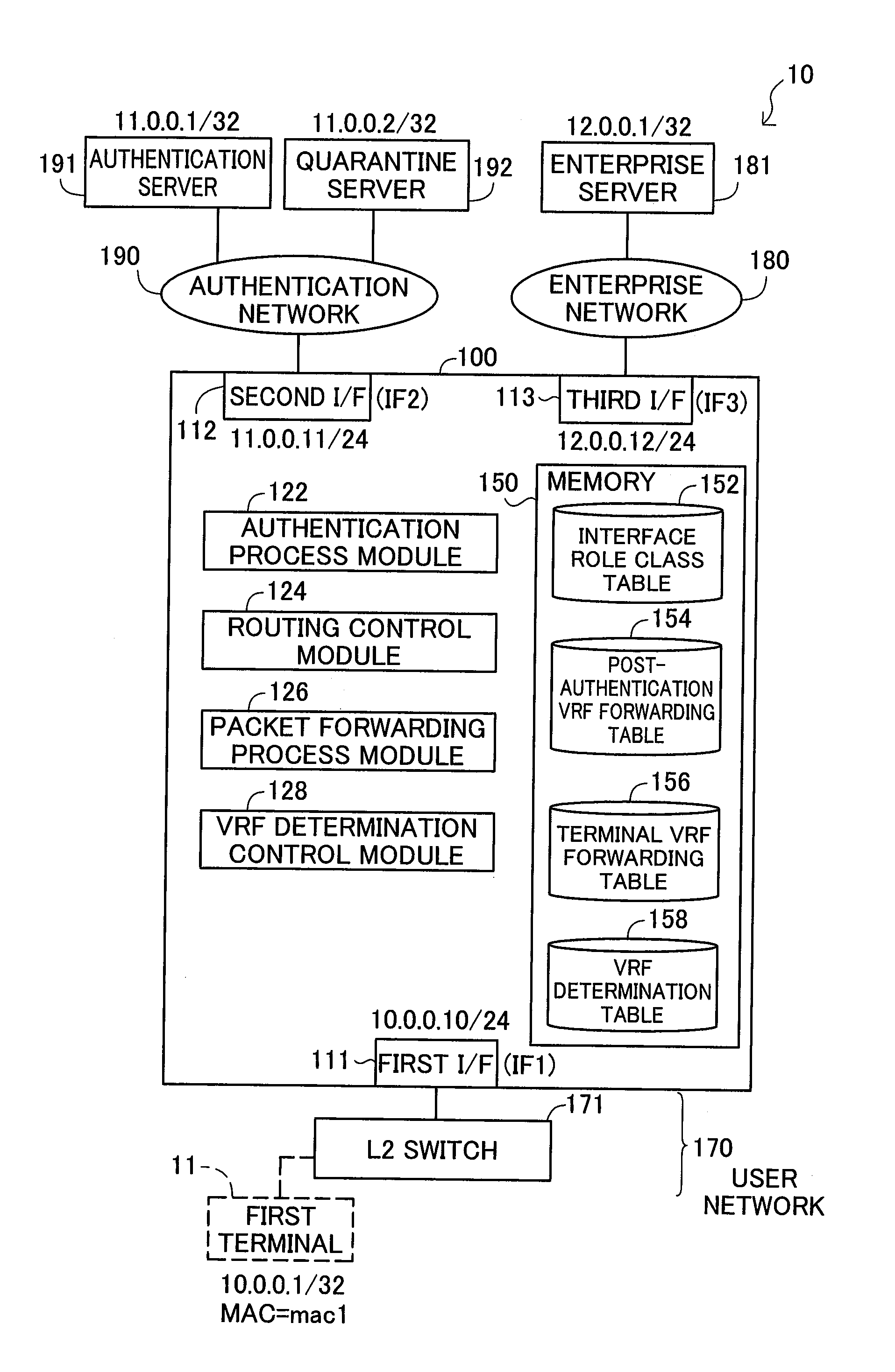
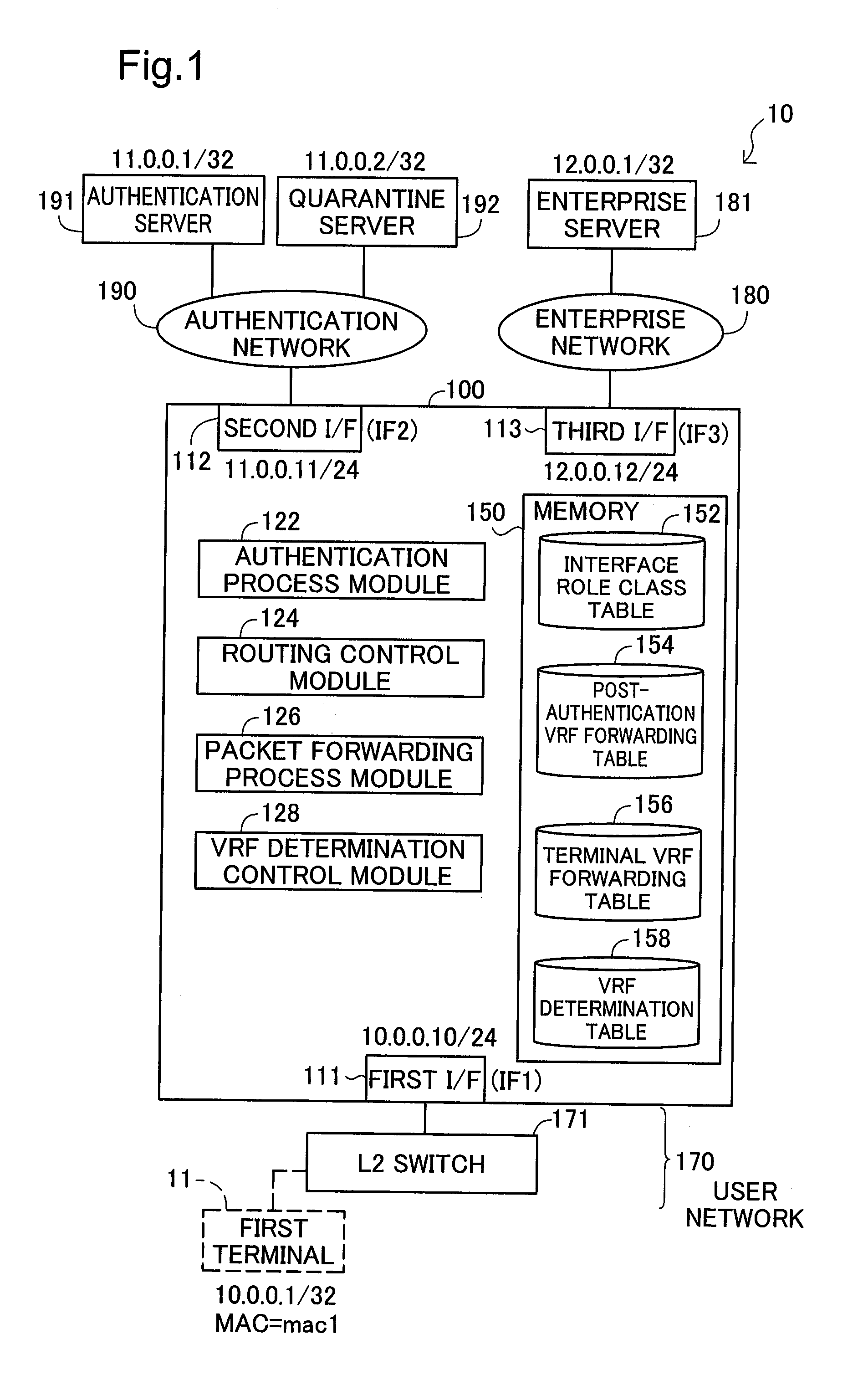
[0116]FIG. 1 is an illustration depicting a configuration of a network system according to a first embodiment of the invention. This network system 10 includes a packet forwarding device 100, a user network 170, a Layer 2 switch 171, an authentication network 190, an authentication server 191, a quarantine server 192, an enterprise network 180, and an enterprise server 181.

[0117]The packet forwarding device 100 is a Layer 3 switch adapted to forward packets in the third layer of the OSI model (the Network Layer). However, a router could be used in place of the Layer 3 switch. In the present embodiment, the third layer packets are IP (Internet Protocol) packets; however, IPX (Internetwork Packet eXchange) packets could be used in place of IP packets. Herein, third layer packets shall be referred to simply as “packets”.

[0118]The packet forwarding device 100 has three interfaces (a first interface 111, a second interface 112, and a third interface...

embodiment 2

B. Embodiment 2

B1. System Configuration

[0176]FIG. 13 is an illustration depicting a configuration of a network system 10a according to a second embodiment of the invention. The following five features of the network system 10a of Embodiment 2 differ from the network system 10 of Embodiment 1, but the configuration is otherwise the same as Embodiment 1. Specifically, the packet forwarding device 100a of Embodiment 2 differs from the network system 10 of Embodiment 1 in that: a fourth interface 114 is provided in addition to the first to third interfaces 111 to 113; the post-authentication VRF forwarding table 154 is replaced by an authentication VRF forwarding table 154a, a first enterprise VRF forwarding table 154b, and a second enterprise VRF forwarding table 154c; the enterprise network 180 is replaced by two enterprise networks (a first enterprise network 180a and a second enterprise network 180b); a second terminal 12 may join the user network 170 in addition to the first termin...

embodiment 3

C. Embodiment 3

[0214]FIG. 27 is an illustration depicting a configuration of a network system according to a third embodiment of the invention. The network system 10b of Embodiment 3 differs from Embodiment 1 in that a router 172 and an access network 200 are provided, but the configuration is otherwise the same as Embodiment 1.

[0215]The router 172 connects to a Layer 2 switch 171 and to the first interface 111 of the packet forwarding device 100, and connects the user network 180 and the access network 200 in Layer 3. The access network 200 is a Layer 3 network (VLAN) provided between the router 172 and the first interface 111. The first terminal 11 is pre-assigned the IP address “20.0.0.1 / 32”.

[0216]Where the first terminal 11 and the first interface 111 are connected via the router 172 in this way, packets (Layer 2 frames) arriving at the first interface 11 from the router 172 have as the sending address (MAC address) a MAC address assigned to a port of the router 172. Consequentl...


PUM


Abstract

A network system includes: a first network; an authentication server; a second network; a network; and a packet forwarding apparatus, wherein the packet forwarding apparatus includes: a forwarding route table storage storing a first forwarding route table containing packet routing information to the second network, and a second forwarding route table containing packet routing information to the second network and the third network; and a forwarding route table selector that, prior to determination of successful authentication for the terminal apparatus, selects the first forwarding route table as a search forwarding route table, and that upon receipt of determination of successful authentication for the terminal apparatus, selects the second forwarding route table as the search forwarding route table.

Description

CROSS-REFERENCE TO RELATED APPLICATIONS[0001]The present application claims priority to Japanese Patent Application No. 2009-185580 filed on Aug. 10, 2009, the disclosure of which is hereby incorporated by reference in its entirety.BACKGROUND OF THE INVENTION[0002]1. Field of the Invention[0003]The present invention relates to technology for forwarding of packets sent by a terminal apparatus.[0004]2. Description of the Related Art[0005]In network systems requiring that authentication or quarantine (hereinafter termed simply “authentication”) be carried out before a terminal (terminal apparatus) can join a network, from a security standpoint there is a need to ensure independence between the network that performs authentication (hereinafter termed simply the “authentication network”) and the network that is accessed subsequent to authentication (which is a different network from the network to which the terminal belongs and from the authentication network (hereinafter termed simply t...

Claims


Application Information

Patent Timeline
IPC IPC(8): H04L12/56H04L29/06H04L12/70H04L12/46H04L12/701
CPCH04L45/54H04L45/72H04L67/2814H04L63/164H04L63/08H04L67/563
Inventor NOZAKI, SHINJIARAI, MASAYA
Owner ALAXALA NETWORKS
Why Eureka
Try Eureka