Radio communication system and transmitting apparatus used for the same

Active Publication Date: 2011-02-10
SHARP KK
View PDF3 Cites 13 Cited by
  • Summary
  • Abstract
  • Description
  • Claims
  • Application Information

AI Technical Summary

Benefits of technology

[0025]According to the present invention, since part of the spread spectrum signals allocated to the frequency channels is deleted so as to reduce the number of sub-carriers for each of the frequency channels, it is possible to provide a greater number of frequency channels, improve frequency efficiency and obtain a high transmission rate in terms of the whole system. Further, since received signals are transformed into frequency-domain signals, which are separated into signals for every frequency channel and subjected to non-linear iterative equalization to reproduce the transmitted signal, it is possible to achieve transmission without degrading performance so much even though the number of sub-carriers available for transmission is lower than the number of signals to be transmitted (the number of signals output from the DFT unit).
[0026]Further, by changing the number of signals to be deleted in accordance with the frequency channel to which spread spectrum signals are allocated, it is possible to allocate frequency channels in conformity with the channel conditions of individual users, hence it is possible to reproduce transmitted data without serious degradation of performance.
[0027]Moreover, by changing the number of signals to be deleted in accordance with the time channel to which spread spectrum signals are allocated, it is possible to provide different frequency channels every time channel, allocate time channels in conformity with the channel conditions of individual users, hence it is possible to reproduce transmitted data without serious degradation of performance.

Problems solved by technology

Since this scheme has high PAPR (Peak-to-Average Power Ratio) performance, it is not suitable as the uplink transmission scheme that is severely limited as to transmission power.

Method used


Image

  • Radio communication system and transmitting apparatus used for the same
  • Radio communication system and transmitting apparatus used for the same
  • Radio communication system and transmitting apparatus used for the same

Examples


first embodiment

The First Embodiment

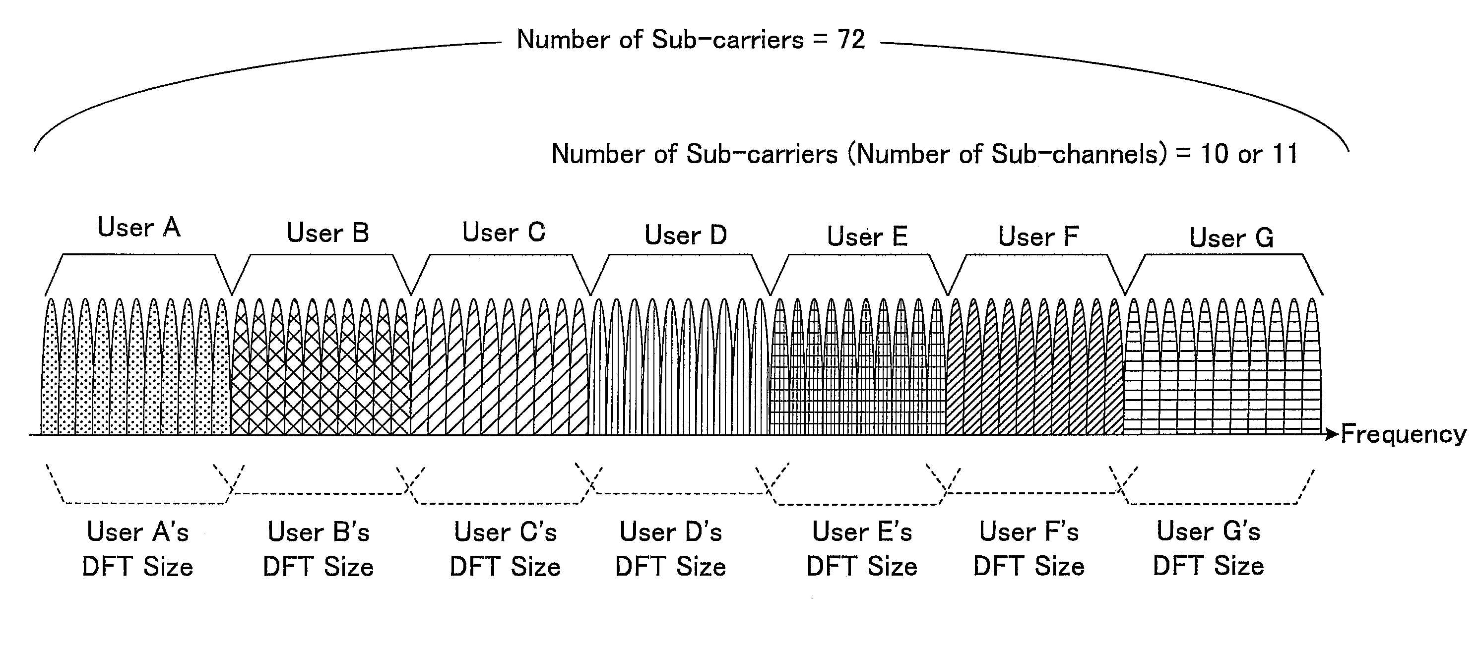
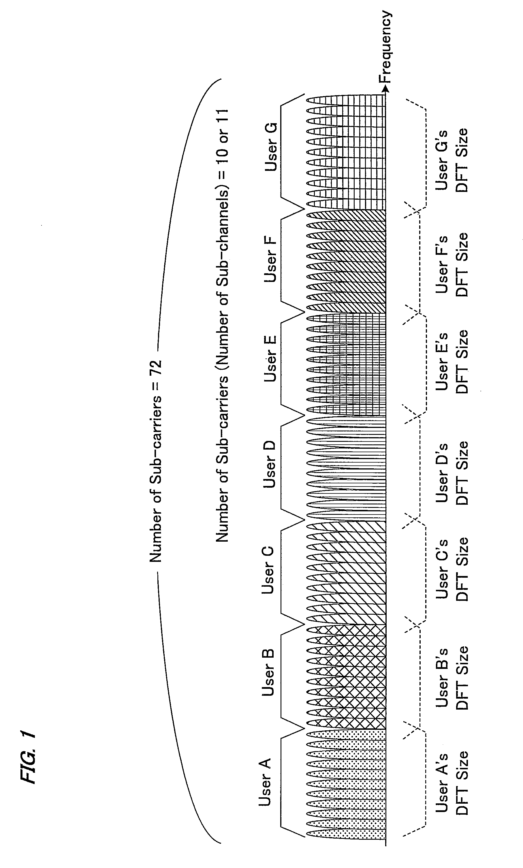
[0042]To begin with, in the present embodiment, a method of allocating sub-carriers in a SC-FDMA system where the number of sub-carriers that constitute one sub-channel is set to be lower than the number of signals output in parallel from the DFT unit of each terminal.

[0043]FIG. 1 shows an example where the present invention is applied to a localized allocation. This FIG. 1 shows an example in which the number of frequency signals (spectrums) that are performed a spread spectrum and output in parallel from the DFT unit of each terminal is 12 (that is, the DFT size is 12), whereas the number of sub-carriers that constitute one sub-channel (one frequency channel) is set at 10 or 11. In this case, the users (users A and G) allocated to the sub-channels (frequency channels) at both ends of the band will not perform transmission of the frequency signal at one end (one sub-carrier) of all the frequency signals output from the DFT unit, whereas the users (users B to F) ...

second embodiment

The Second Embodiment

[0054]This embodiment shows a configuration of a receiving apparatus (base station apparatus) that, when receiving a signal from which part of spectrums was clipped off, can reproduce the transmitted data without degrading performance too much by using non-liner iterative equalization having an excellent interference reducing function (e.g., frequency domain SC / MMSE (Soft Canceller followed by Minimum Mean Square Error) turbo equalization).

[0055]FIG. 5 shows a base station apparatus in the present embodiment. As shown in FIG. 5, the base station apparatus in the present embodiment includes a receiving antenna unit 200, a radio unit 201, an A / D converter 202, a synchronizer 203, a CP remover 204, a S / P converter 205, a DFT unit 206, a sub-carrier demapping unit 207, a zero inserter 208, a canceller 209, an equalizer 210, an IDFT unit 211, a demodulation and error correction decoder 212, an iteration controller 213, a decision unit 214, a channel estimator 215, a ...

third embodiment

The Third Embodiment

[0065]This embodiment shows an example where the number of frequency signals to be clipped varies every time-channel (frame). FIG. 6 shows a relationship between frames and sub-channels in the present embodiment. Here, though not illustrated in FIG. 6, each frame is formed of a plurality of symbols. As shown in FIG. 6, in the present embodiment, a different number of frequency signals are clipped for every frame so as to provide a different number of sub-channels (the maximum user capacity) in every frame. For example, the number of frequency signals to be clipped from each user allocated in frame 1 in FIG. 6 is two so that seven sub-channels can be provided. On the other hand, in frame 2, no clipping is performed for every user, the number of sub-channels is six. Further, the number of sub-channels in frame 3 is eight, and three frequency signals are clipped from each user allocated to this frame. In this way, the number of frequency signals to be clipped is set...


PUM


Abstract

To provide a system that can accommodate a greater number of terminals within a limited band and can obtain a higher transmission rate. While the number of frequency signals (spectrums) output in parallel by performing a spread spectrum from the DFT unit of each terminal is 12, the number of sub-carriers constituting one sub-channel is set at 10 or 11. In this case, the users (users A and G) allocated to the sub-channels at both ends of the band will not perform transmission of one frequency signal at the end (one sub-carrier) of all the frequency signals output from the DFT unit, whereas the users (users B to F) allocated to the other sub-channels will not perform transmission of the frequency signals at the ends (two sub-carriers). This transmission can be realized by deleting (clipping) the associated number of signals from both ends or from one end of the frequency signals output from the DFT unit of each terminal and allocating the frequency signals after clipping, to individual sub-channels.

Description

TECHNICAL FIELD[0001]The present invention relates to a radio communication system that can accommodate a greater number of terminals within a limited band and can obtain a higher transmission rate, by setting up a lower number of sub-carriers that constitute one sub-channel compared to the number of signals output in parallel from the DFT unit of each terminal, as well as relating to a transmitting apparatus for use in the system.BACKGROUND ART[0002]With recent increase in volume of data communication, the need for a mobile communication system that has a higher frequency usage efficiency has been increased and various studies on one cell reuse cellular system that uses the same frequency band in all the cells have been proceeded. In E-UTRA (Evolved Universal Terrestrial Radio Access) system which is one of one cell reuse cellular systems and has been advanced to be standardized by mainly 3GPP (3rd Generation Partnership Project), the OFDMA (Orthogonal Frequency Division Multiple A...

Claims


Application Information

Patent Timeline
IPC IPC(8): H04B1/707
CPCH04J11/00H04L5/0039H04L27/2636H04W72/06H04L25/03171H04W72/563
Inventor TO, SHIMPEIKUBOTA, MINORUHAMAGUCHI, YASUHIRONAKAMURA, OSAMUYOKOMAKURA, KAZUNARISAMPEI, SEIICHIMIYAMOTO, SHINICHIIBI, SHINSUKE
Owner SHARP KK
Why Eureka
Try Eureka