Metal shell manufacturing structure and method

Inactive Publication Date: 2011-02-10
HUANG MAO LIEN
View PDF2 Cites 4 Cited by
  • Summary
  • Abstract
  • Description
  • Claims
  • Application Information

AI Technical Summary

Benefits of technology

[0007]A main object of the present invention is to provide a metal shell manufacturing structure and method which can simplify the metal shell manufacturing process and dispose various components on metal surfaces in a simple process, thereby reducing the costs and saving time.
[0014]In the metal shell manufacturing structure and method of the present invention, the formed plastic layers are fastened in the fixing grooves directly and the plastic layers and the assembling holes can be formed in one piece via a mold, so there is no need for cutting a hole separately and welding the assembling poles like prior arts, thereby simplifying the manufacturing process, reducing the costs, saving time and maximizing the efficiency for manufacturing metal shells.

Problems solved by technology

However, the above-mentioned manufacturing method is very complicated: the size of the positioning hole 2a must be very accurately defined, and each positioning hole 2a needs to be cut separately and each assembling pole 3a needs to be positioned and welded separately.
So the more the components desired to be mounted are, the more the repeated steps are, which causes that the operation time is prolonged, the probability of failure is high, and the costs are quite high.

Method used


Image

  • Metal shell manufacturing structure and method
  • Metal shell manufacturing structure and method
  • Metal shell manufacturing structure and method

Examples


Embodiment Construction

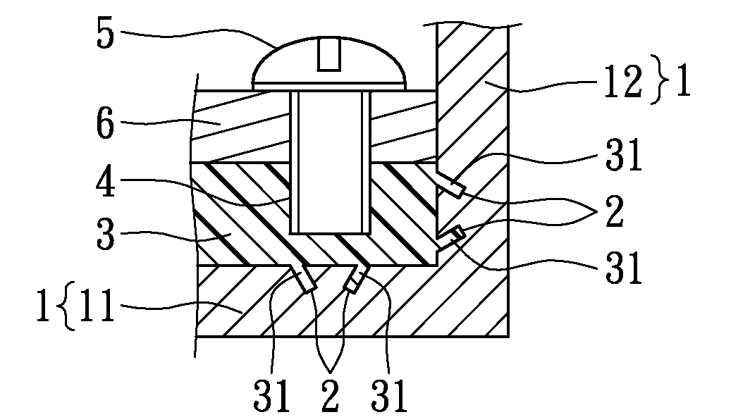
[0032]Please refer to FIGS. 3A-3C, FIGS. 4A-4C, FIGS. 5A-5C and FIGS. 6A-6C, illustrating a metal shell manufacturing structure according to the present invention. The metal shell manufacturing structure includes a metal substrate 1, at least one fixing groove 2, at least one plastic layer 3 and at least one assembling hole 4. The fixing grooves 2 are formed in the metal substrate 1, the plastic layers 3 are disposed on the metal substrate 1, the plastic layers 3 are fastened in the fixing grooves 2, and the assembling holes 4 are formed in the plastic layers 3.

[0033]As shown in FIGS. 3A-3C, the metal substrate 1 originally is a smooth surface. The fixing grooves 2 are formed in a position desired to be manufactured of the metal substrate 1, by a drilling machine, a lathing machine, a punching machine, a milling machine or other machining equipments. The fixing grooves 2 extend into the metal substrate 1 from a surface of the metal substrate 1. In the cross-sectional view, the fixin...


PUM

PropertyMeasurementUnit
Angleaaaaaaaaaa

Abstract

The present invention discloses a metal shell manufacturing structure and method. The structure includes a metal substrate, at least one fixing groove, at least one plastic layer, and at least one assembling hole. The fixing groove is formed in the metal substrate and extends into the metal substrate from a surface of the metal substrate. The plastic layer is disposed on the metal substrate and fastened in the fixing groove. The assembling hole is formed in the plastic layer and extends into the plastic layer from a surface of the plastic layer. The formed plastic layer is fastened in the fixing groove directly and the plastic layer and the assembling hole can be formed in one piece via a mold, thereby simplifying the manufacturing process, reducing the costs and saving time. The present invention further discloses a metal shell manufacturing method.

Description

BACKGROUND OF THE INVENTION[0001]1. Field of the Invention[0002]The present invention relates to a metal shell manufacturing structure and method, and more particularly to a metal shell manufacturing structure and method which can manufacture metal shells so that various components are disposed on metal surfaces.[0003]2. Description of Related Art[0004]With the development of science and technology, various electronic products and electronic equipments occur. Metal manufacture is generally applied in these electronic products and electronic equipments, including external shell assembly and internal mechanism arrangement. Especially, internal mechanisms always have many functional components mounted therein, and the functional components need to be securely disposed in metal shells by metal manufacturing. Taking notebook computers for example, hardware, such as motherboards, hard disks, power supplies and so on, are mounted and fixed in metal shells.[0005]As shown in FIG. 1A and FIG....

Claims


Application Information

Patent Timeline
IPC IPC(8): B32B3/10B23P11/00
CPCG06F1/1615G06F1/183Y10T29/49826Y10T29/49947Y10T428/24331
Inventor HUANG, MAO-LIEN
Owner HUANG MAO LIEN
Why Eureka
Try Eureka