Lumen diameter and stent apposition sensing

a technology of stent apposition and lumen diameter, applied in the field of medical science, can solve the problems of increasing stenosis and other well known negative effects, cr stents, and current x-ray tools are not sufficient to judge apposition, and achieve the effect of slowing down and increasing impedan

Inactive Publication Date: 2011-02-10
GELBART DANIEL +1
View PDF12 Cites 67 Cited by
  • Summary
  • Abstract
  • Description
  • Claims
  • Application Information

AI Technical Summary

Benefits of technology

[0005]A stent balloon is provided with two conductive rings, created by a thin metallized coating deposited directly on the balloon, adjacent to the ends of the stent. The impedance between those rings and the body of the patient is measured at different AC frequencies. As the balloon approaches the vessel wall the impedance increases rapidly. Once the balloon forms full contact with vessel wall the impedance increases slowly. The changing impedance provides a guide for optimal apposition of the stent.

Problems solved by technology

Both under expansion and over expansion are undesirable, causing increased stenosis and other well known negative effects.
The current x-ray tools are not sufficient to judge the apposition because of at least three reasons: lack of resolution, the fact that vessel wall is visible only for a short time when a dye is injected and the fact that the current x-ray system only provides a view from a single viewing angle.
This problem is mainly found in the Co—Cr stents.
Stent longitudinal slippage relative to balloon is mainly a problem with stents that are crimped on before use at the hospital, as the crimping is less controlled than the crimping and bonding done at the factory.
Such sensors increase the diameter and complexity of the balloon, as the capacitor is formed between two conductors separated by a dielectric.
The small size does not allow for any device that may significantly increase the diameter of the balloon in the collapsed state.
The sensors of the '858 patent add significant thickness and complexity to the collapsed balloon which has to be as small as 1 mm for some applications.
Again, since the design is based on an electronic integrated circuit built into the stent it is not suitable to small diameter stents.
The prior art also greatly increases the cost of the stents.
Another problem with prior art impedance measurement is that the actual impedance of the vessel wall is unknown, as the wall can be clean or covered by various types of plaque.

Method used


Image

  • Lumen diameter and stent apposition sensing
  • Lumen diameter and stent apposition sensing
  • Lumen diameter and stent apposition sensing

Examples


Embodiment Construction

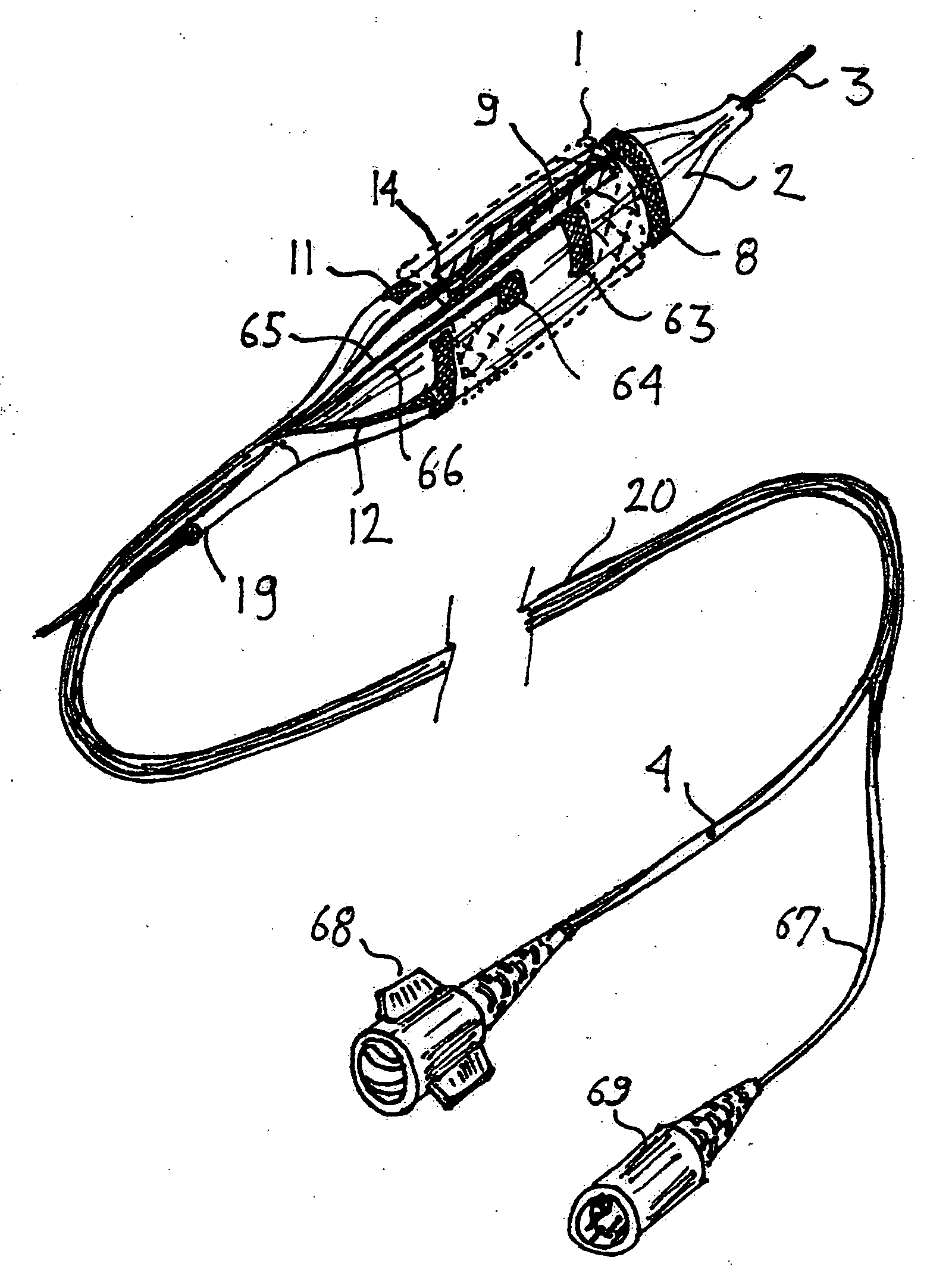
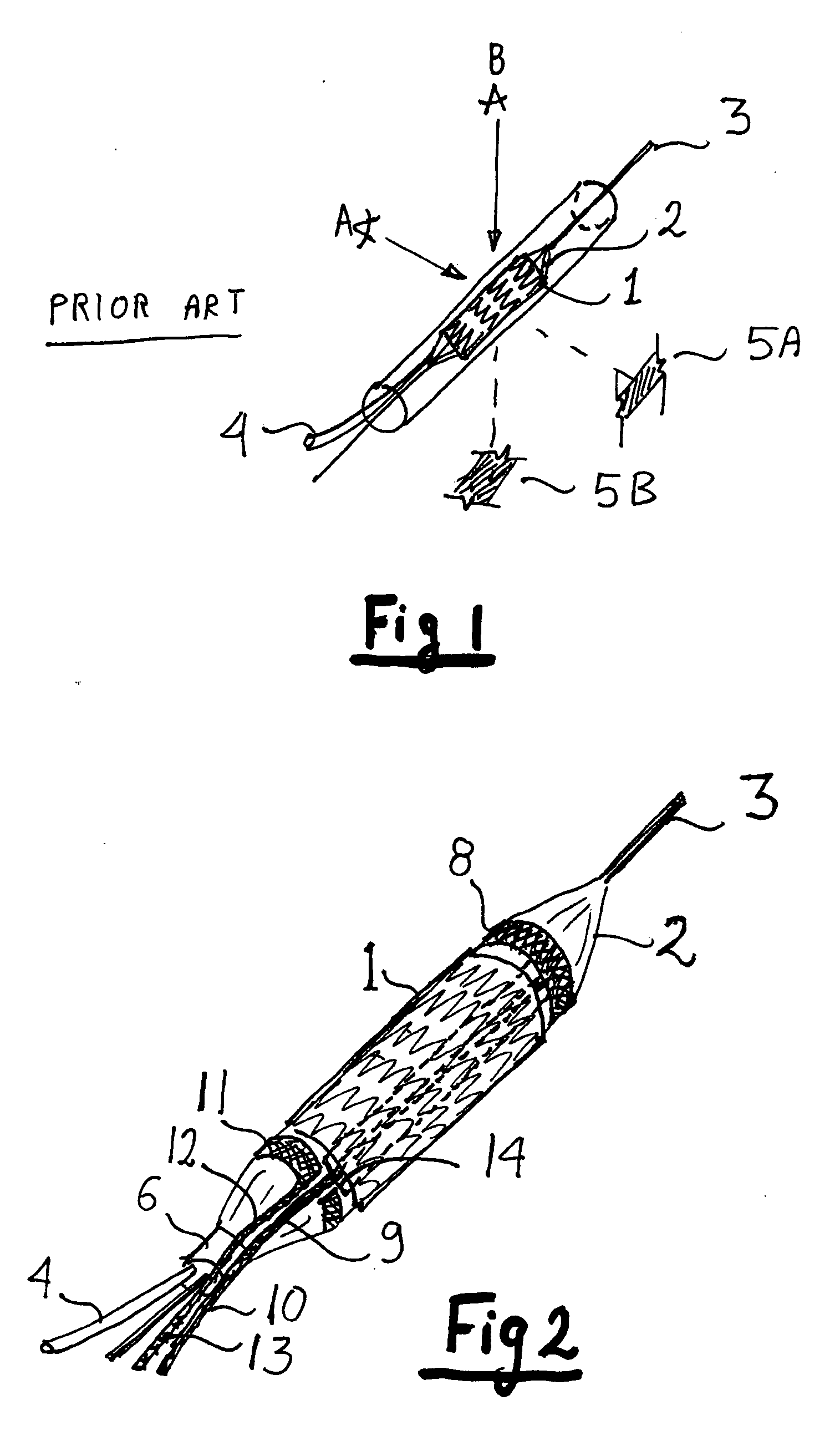
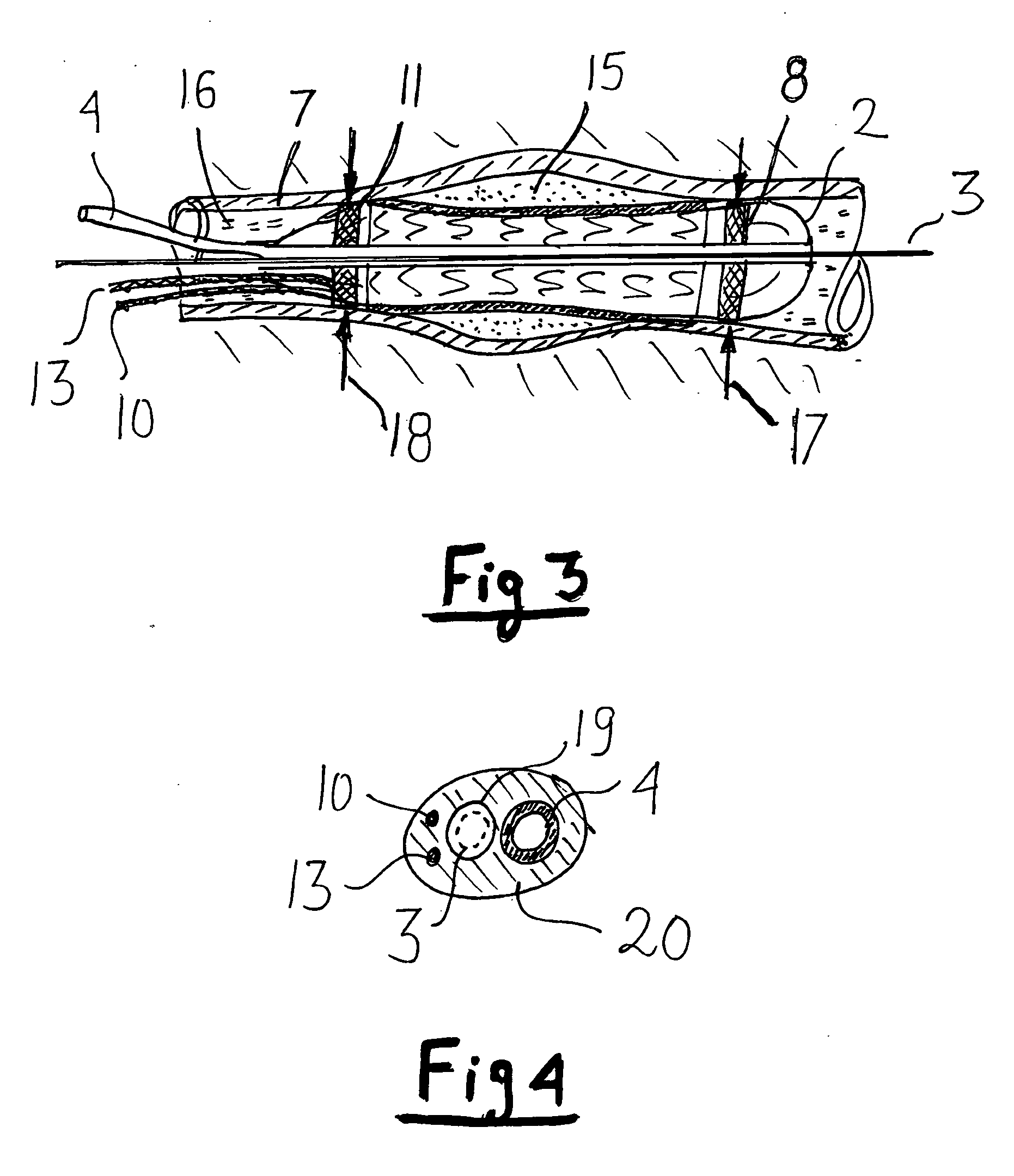
[0015]Referring now to FIG. 2, a stent 1 is expanded by balloon 2 connected to a pressurizing tube 4 and guided by guide wire 3. As the art of stents and stenting is well known, no further details are given. The balloon has a distal ring electrode 8 and a proximal ring electrode 11 preferably formed by metallizing the pattern directly onto the balloon. The art of metallizing polymers is well known and used extensively is packaging materials. It can be done by vacuum evaporation, sputtering or chemical deposition. The advantage of metallization is that significant conductivity can be achieved without increasing the diameter of the balloon and without affecting its mechanical properties. A typical thickness of a metallized layer is below 1 micron and can be as thin as 0.1 um. Many metals are suitable for the metallized electrodes, such as aluminum, gold, or nickel. The ductility of the coating can be increased by using a serpentine-like pattern but even a solid area will withstand the...


PUM


Abstract

A stent balloon is provided with two conductive rings, created by a thin metallized coating deposited directly on the balloon, adjacent to the ends of the stent. The impedance between those rings and the body of the patient is measured at different AC frequencies. As the balloon approaches the vessel wall the impedance increases rapidly. Once the balloon forms full contact with vessel wall the impedance increases slowly. The changing impedance provides a guide for optimal apposition of the stent.The same conductive rings can also detect stent slippage and stent position relative to the balloon. With the addition of an extra conductive pad and wire, stent spring-back can be measured and corrected for.

Description

FIELD OF THE INVENTION[0001]The invention is in the medical field and in particular in the field of stenting.BACKGROUND OF THE INVENTION[0002]The art of keeping bodily lumens open by using stents is well known and used not only in the vascular system but also for other lumens in the body, such as in the digestive and renal system. In general two conditions need to be met when a stent is deployed: the ends have to have full contact with the lumen along their circumference and the central section has to be sufficiently open. In an ideal stent apposition the ends form a smooth transition to the vessel wall. Both under expansion and over expansion are undesirable, causing increased stenosis and other well known negative effects. The most common use of stents is in the arterial system. The stenting is performed under x-ray (fluoroscopy). The current x-ray tools are not sufficient to judge the apposition because of at least three reasons: lack of resolution, the fact that vessel wall is v...

Claims


Application Information

Patent Timeline
Patent Type & Authority Applications(United States)
IPC IPC(8): A61B5/05A61F2/82
CPCA61F2250/0043A61F2/958
Inventor GELBART, DANIELMACHAN, LINDSAY S.
Owner GELBART DANIEL
Why Eureka
Try Eureka