Fail-Safe Silicone Breast Implant Delivery Device

a silicone breast implant and delivery device technology, applied in mammary implants, prostheses, medical science, etc., can solve the problems of apprehension about selecting silicone implants, large access incisions, and time-consuming hand manipulation even for a highly-skilled surgical practitioner, so as to avoid damage to implants and/or further fuss or fiddle, avoid apprehension about silicone implants, and facilitate the preparation

a silicone breast implant and delivery device technology, applied in mammary implants, prostheses, medical science, etc., can solve the problems of apprehension about selecting silicone implants, large access incisions, and time-consuming hand manipulation even for a highly-skilled surgical practitioner, so as to avoid damage to implants and/or further fuss or fiddle, avoid apprehension about silicone implants, and facilitate the preparation

US20110035003A1Active Publication Date: 2011-02-10KELLER MEDICAL

Image

  • Fail-Safe Silicone Breast Implant Delivery Device
  • Fail-Safe Silicone Breast Implant Delivery Device
  • Fail-Safe Silicone Breast Implant Delivery Device

Examples


Embodiment Construction

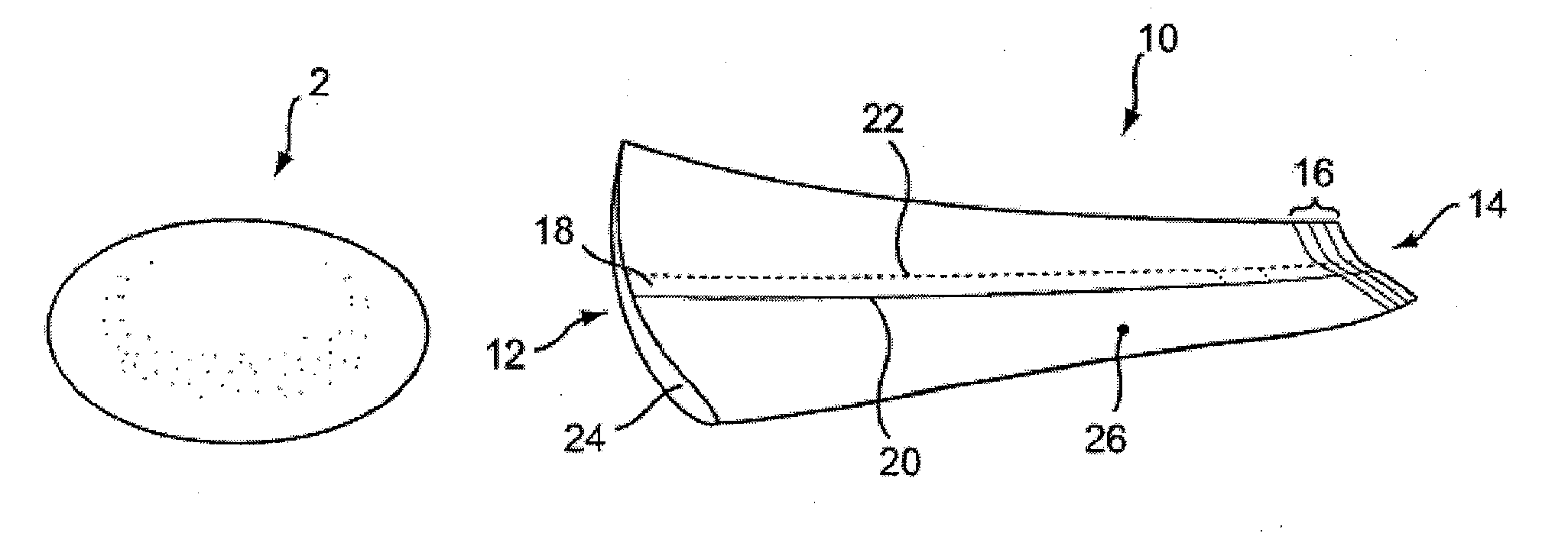
[0035]FIG. 1 illustrates a pre-filled silicone implant 2 and sleeve 10 according to the present invention provided to facilitate implant delivery. Sleeve 10 has general conical shape that defines a first opening 12 at a larger end and a smaller opening 14 at a terminal end.

[0036]The tip of the device may include indicia 16 coordinated to various implant sizes to facilitate trimming the opening to the correct size. The indicia provide a guide for a practitioner to cut along a selected line in order to size the exit diameter of the device for a given implant in a size range, for example, of between about 150 cc to about 800 cc. By so trimming the sleeve, exit diameters from between about 3 cm to about 6 cm are provided. For a more typical range of implant sizes, the openings may be sized approximately as follows (width dimension measured with the sleeve laid flat): 4.5 cm for 300 cc implants, 5.0 cm for 300 cc to 450 cc implants, and 5.5 cm for 450 cc to 550 cc implants.

[0037]Sleeve 1...


PUM


Abstract

A tapered sleeve is provided for implant delivery. An implant (e.g., a pre-filled silicone breast implant) is introduced into a large proximal end of the sleeve and extruded into a surgical pocket of minimal access incision size through a small-sized distal end of the device. Sized appropriately to the implant, the sleeve remains intact during implant run-through of the sleeve.

Description

CROSS-RELATED APPLICATION[0001]This application is a continuation-in-part of U.S. patent application Ser. No. 12 / 387,215, filed Apr. 29, 2009, which is fully incorporated herein by reference.BACKGROUND[0002]Silicone breast implants were re-approved in the United States in November, 2006, after having been withdrawn from the market. Implant recipients cite safety, scarring, and “natural” look and feel to be the top three indicators in selecting between saline- and silicone-filled implants for breast augmentation. Given that the more natural look and feel offered by silicone is a pre-requisite for many patients, silicone implants have already achieved nearly 50% market share following their return to the market.[0003]But because silicone implants are pre-filled (to alleviate leakage concerns) they have generally required larger access incisions than saline implants. Due to the possibility of visible scars associated with the larger incisions, some patients have remained apprehensive a...

Claims


Application Information

Patent Timeline
10 Feb 2011
Publication
US20110035003A1
IPC
A61F2/52
CPC
A61F2/12; A61F2230/0067; A61F2250/0071; A61F2250/0097
Inventors
PREISSMAN, HOWARD E.