
Hydraulic system with a pressure ripple reduction device

Active Publication Date: 2011-02-17
POWER PACKER NORTH AMERICA INC
View PDF15 Cites 2 Cited by
  • Summary
  • Abstract
  • Description
  • Claims
  • Application Information

AI Technical Summary

Benefits of technology

[0017]By the provision of an expansion chamber according to the above characteristics, the pressure ripples are reduced by energy loss. This means that pressure ripples are not cancelled merely by a 180 degrees phase shift and consequently that the expansion chamber can handle multiple frequencies, i.e. the expansion chamber acts as a broadband dampening device. Hence, a very simple and cost effective solution for the reduction of a range of frequencies in pressure ripples in an hydraulic system is provided.
[0024]In an embodiment the outlet comprises an insert element comprising a through bore defining the cross-sectional area of the outlet. This provides an easy and well controllable way of providing the outlet with a desired cross-sectional area.

Problems solved by technology

A ratio between 5 and 40000 has been found to provide good results while still being practical for normal hydraulic systems, wherein a ratio of 40000 is a practical upper limit in view of pressure drop over the pressure reduction device and a ratio of less than 5 may not yield satisfactory results.

Method used


Image

  • Hydraulic system with a pressure ripple reduction device
  • Hydraulic system with a pressure ripple reduction device
  • Hydraulic system with a pressure ripple reduction device

Examples


Embodiment Construction

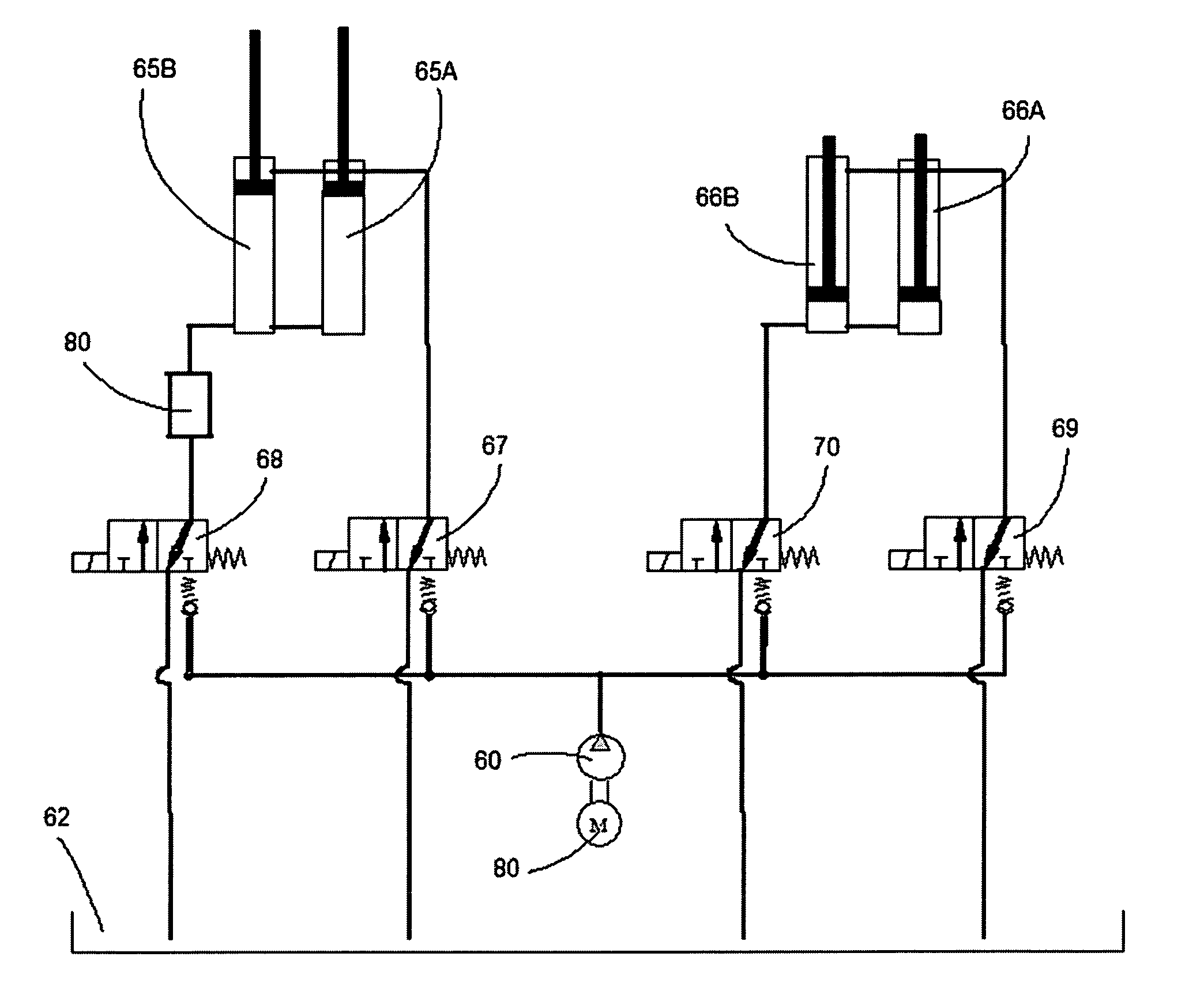
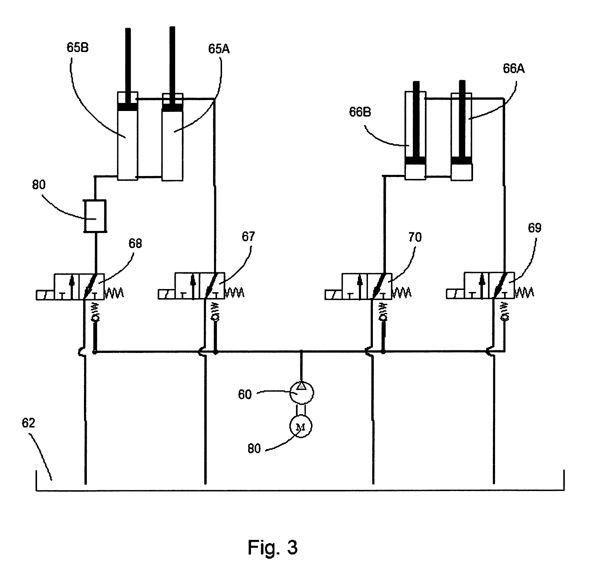
[0036]The hydraulic system according to the invention is particularly suitable to be used in vehicles having moveable components. In particular in luxury vehicles such as large SUV's having large tailgates or convertibles having convertible or foldable roofs non-manual operation of such components contribute to the overall feel of luxury and practicality of the car.

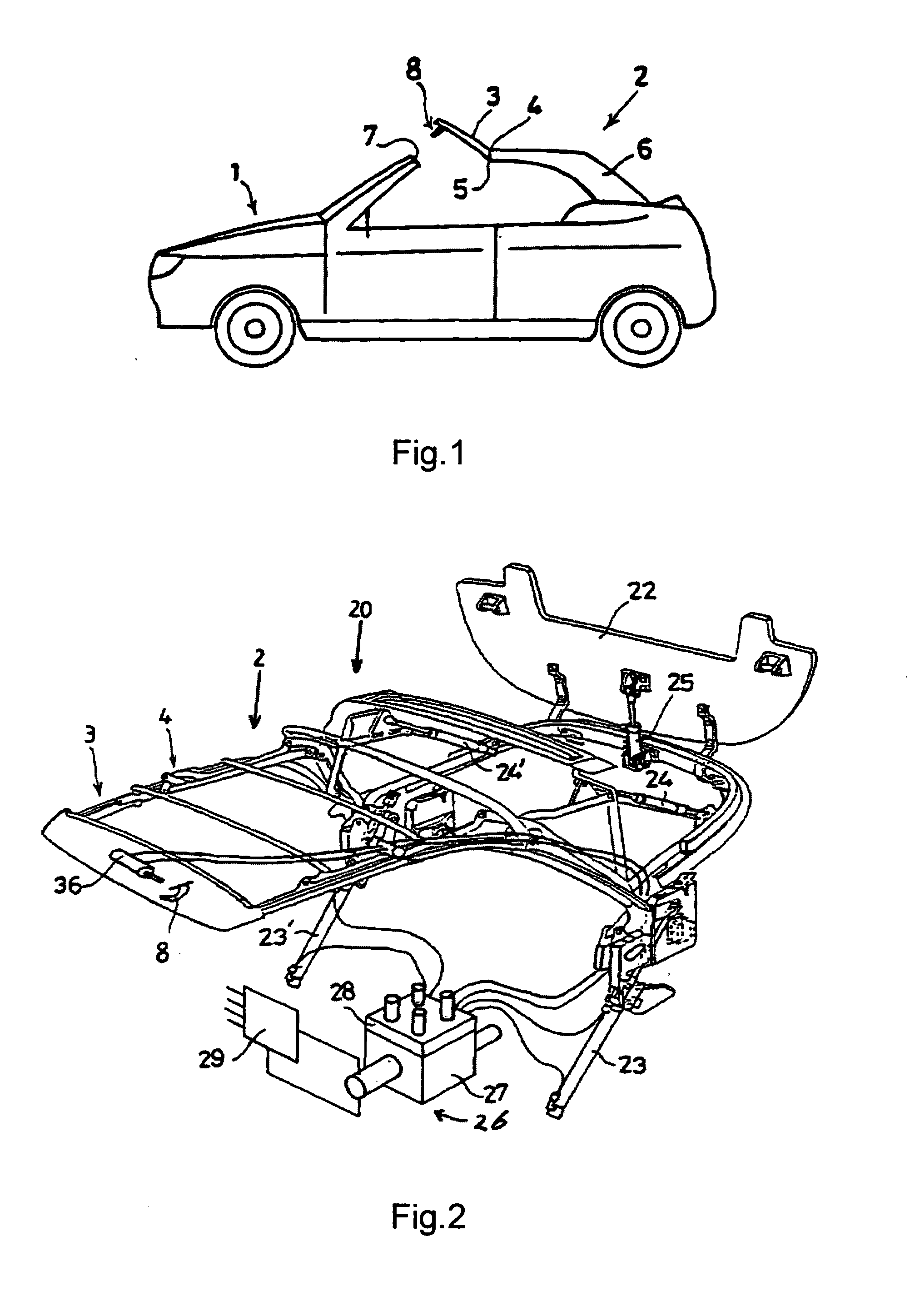
[0037]As an example of the use of a hydraulic system according to the invention is described below in combination with a convertible roof for a car, in which the car comprises a convertible top assembly having a hydraulic actuating device for opening and closing the convertible top assembly.

[0038]FIG. 1 shows a car 1 of the convertible type, having a folding roof 2 of a mechanical design which is known per se and which can be used to open or close the passenger compartment. The folding roof 2 has a front folding-roof part 3 which is attached to the remaining part 6 of the folding roof 2 via a pivoting attachment 4 about p...


PUM


Abstract

A hydraulic system for a vehicle, comprising a hydraulic actuation device for moving one or more moveable components of the vehicle. The actuation device comprises a hydraulic pump with an associated drive means, a reservoir for hydraulic fluid as well as one or more hydraulic actuators connected to the pump through hydraulic hoses. The hydraulic actuators act on the one or more moveable components. The pump is designed to supply pressurized hydraulic fluid to the one or more hydraulic actuators. A pressure ripple reduction device for reducing pressure ripples in the hydraulic fluid originating from the hydraulic pump is provided, having an expansion chamber.

Description

CROSS-REFERENCE TO RELATED APPLICATIONS[0001]This application claims the benefit of PCT International Application No. PCT / EP2009 / 003424 filed on Apr. 22, 2009, which claims the benefit of European Patent Application No. 08075313.0 filed on Apr. 23, 2008, both of which are incorporated herein by reference.STATEMENT CONCERNING FEDERALLY SPONSORED RESEARCH OR DEVELOPMENT[0002]Not applicable.FIELD OF THE INVENTION[0003]The present invention relates to a hydraulic system for a vehicle for reducing pressure ripples.BACKGROUND OF THE INVENTION[0004]Hydraulic systems designed to move moveable components are for example used in vehicles such as cars and trucks. Taking the example of cars used for personal transport, such hydraulic systems are for example used for convertibles in which the convertible top can move from a closed position, in which the convertible top covers the passenger compartment of the vehicle, and an open position in which the passenger compartment is open. Similarly, suc...

Claims


Application Information

Patent Timeline
IPC IPC(8): F16D31/02
CPCB60J7/1273F15B21/008F15B2211/20515F15B2211/8616F15B2211/3057F15B2211/7128F15B2211/20538
Inventor VAN'T VEEN, DANIEL
Owner POWER PACKER NORTH AMERICA INC
Learn More