Tumble Dryer with a Heat Pump System and a Method for Controlling a Heat Pump System for a Tumble Dryer

a technology of heat pump and tumble dryer, which is applied in the direction of process control, lighting and heating equipment, instruments, etc., can solve the problems of compressor operation parameters that cannot be controlled during the operation, compressor design is very complex, and needs a large space, so as to reduce the rotation speed of the compressor

Inactive Publication Date: 2011-02-17
ELECTROLUX HOME PROD CORP NV
View PDF10 Cites 20 Cited by
  • Summary
  • Abstract
  • Description
  • Claims
  • Application Information

AI Technical Summary

Benefits of technology

[0031]In a preferred embodiment, the method according to the present invention provides for a reduction of rotation speed of the compressor after a delay time interval (DTI) has elapsed from the detection of the maximum temperature value of the refrigerant at evaporator outlet.

Problems solved by technology

The design of the compressor is very complex.
This compressor is very big and needs a large space.
Such a compressor works in an on / off-mode, so that the operating parameters of said compressor cannot be controlled during the operation.
The reduced rotation speed of the compressor is sufficient and saves energy, since the excess of energy could not be used and would be lost.
The reduced rotation speed of the compressor is sufficient for the further drying procedure and saves energy, since the excess of additional energy could not be used and would be lost.
Further, the physical parameter may be the electrical impedance of the laundry within the drum, which electrical impedance increases with the increasing dryness of the laundry.

Method used


Image

  • Tumble Dryer with a Heat Pump System and a Method for Controlling a Heat Pump System for a Tumble Dryer
  • Tumble Dryer with a Heat Pump System and a Method for Controlling a Heat Pump System for a Tumble Dryer
  • Tumble Dryer with a Heat Pump System and a Method for Controlling a Heat Pump System for a Tumble Dryer

Examples


Embodiment Construction

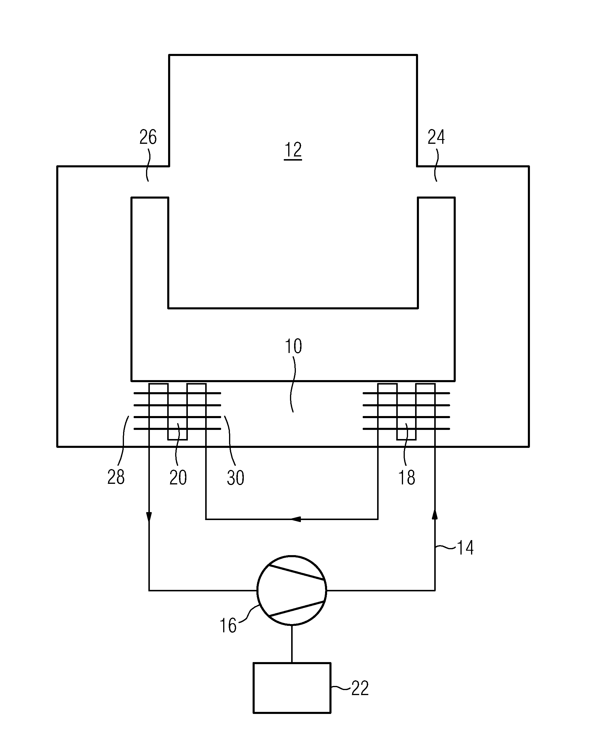
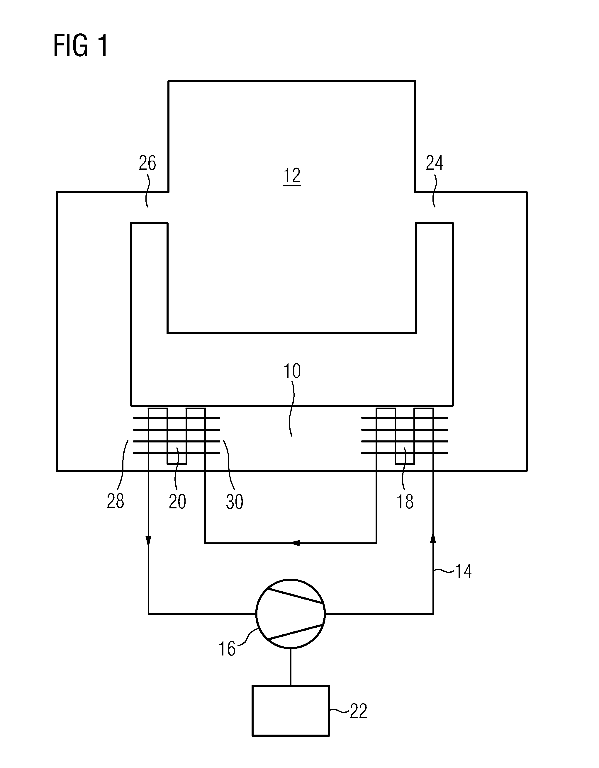
[0043]FIG. 1 illustrates a schematic diagram of a tumble dryer with a heat pump system according to a preferred embodiment of the present invention. In FIG. 1, only the substantial components of the tumble dryer with the heat pump system are shown. The tumble dryer with a heat pump system comprises an air stream circuit 10, a drum 12, a refrigerant circuit 14, a compressor 16, a first heat exchanger 18, a second heat exchanger 20 and a control unit 22.

[0044]The drum 12 is an integrated part of the air stream circuit 10. The drum 12 is provided for receiving laundry. In a similar way, the compressor 16 is an integrated part of the refrigerant circuit 14. The air stream circuit 10 and the refrigerant circuit 14 are thermally coupled by the first heat exchanger 18 and the second heat exchanger 20. The first heat exchanger works as a condenser 18. The second heat exchanger works as an evaporator 20. The control unit 22 is provided for controlling the compressor 16. In particular, the co...


PUM


Abstract

A tumble dryer with at least one heat pump system has an air stream circuit (10) including at least one drum (12) for receiving laundry to be dried, at least one refrigerant circuit (14) including at least one compressor (16) with a variable rotation speed, a first heat exchanger (18) for a thermal coupling between the air stream circuit (10) and the refrigerant circuit (14), and a second heat exchanger (20) for a further thermal coupling between the air stream circuit (10) and the refrigerant circuit (14). The tumble dryer further includes a control unit (22) for controlling the rotation speed of the compressor (16) and at least one sensor for detecting at least one physical parameter (TDI, TDO; TEI, TEO; TF; Z; RH) as function of the time of the air stream, the refrigerant ad/or the laundry. A central processing unit is provided, which is arranged to evaluate the time development of the physical parameter (TDI, TDO, TEI, TEO; TF; Z; RH) and which reduces the rotation speed of the compressor (16) according to the evaluation of the time development of the physical parameter (TDI, TDO, TEI, TEO; TF; Z; RH). A corresponding method for controlling a heat pump system for a tumble dryer is also set forth.

Description

CROSS-REFERENCE TO RELATED APPLICATION[0001]This application claims priority under 35 U.S.C. §119 to European application EP 09010370.6, filed Aug. 12, 2009.BACKGROUND OF THE INVENTION[0002]The present invention relates to a tumble dryer with a heat pump system. Further, the present invention relates to method for controlling a heat pump system.[0003]For a tumble dryer, the heat pump technology is a very efficient way to save energy. A usual tumble dryer with heat pump technology uses a reciprocating fixed speed compressor for the refrigerant circuit. This type of compressor has several disadvantages. The design of the compressor is very complex. This compressor is very big and needs a large space. Such a compressor works in an on / off-mode, so that the operating parameters of said compressor cannot be controlled during the operation.[0004]DE 10 2005 041 145 A1 discloses a tumble dryer with a heat pump system. The refrigerant circuit of said heat pump system includes a compressor wit...

Claims


Application Information

Patent Timeline
Patent Type & Authority Applications(United States)
IPC IPC(8): G05D23/00D06F58/04F25B27/00F25B49/02D06F58/48
CPCD06F58/206Y02B40/72D06F2058/287D06F58/28D06F2103/50D06F2105/26Y02B40/00D06F2103/10D06F58/48D06F2103/04D06F2103/32D06F2103/34
Inventor BISON, ALBERTOZANDONA', STEFANOUGEL, MAURIZIO
Owner ELECTROLUX HOME PROD CORP NV
Why Eureka
Try Eureka