Systems, machines, devices and methods for efficiently removing sidewalk trip hazards

a technology of system and machine, applied in the field of systems, can solve the problems of time-consuming and proved too expensive, and achieve the effect of less time-consuming and less expensiv

Active Publication Date: 2011-02-17
BOLLINGER KEVIN
View PDF25 Cites 16 Cited by
  • Summary
  • Abstract
  • Description
  • Claims
  • Application Information

AI Technical Summary

Benefits of technology

[0007]One early solution to these problems, as shown in U.S. Pat. No. 5,116,162, was to grind away only the offending offset. However, this was time consuming, not significantly less expensive, and created substantial amounts of concrete dust, which is a health hazard itself. In response to these problems in grinding away the offending offset, as shown in U.S. Pat. No. 6,863,062, a further solution was to cut away the offending offset using a rotating concrete saw and blade, by plunging the blade into the top surface of the concrete slab. This solution avoided creating as much concrete dust, and the actual concrete cutting is less time consuming than grinding away the offending offset. However, moving the concrete cutting device disclosed in the 062 patent from one trip hazard location to the next and setting up that concrete cutting device at each trip hazard location was itself time consuming and complicated.
[0008]Other solutions directed to concrete cutting, such as those shown in U.S. Pat. Nos. 6,827,074; 6,896,604; 7,000,606; 7,143,760; 7,201,644 and 7,402,095, use hand-held right-angle grinders to cut off the offending offset, again by plunging the saw blade into the top surface of the concrete slab. Using hand-held right-angle grinders does not require long set-up times and allows the workers to quickly and easily move from one trip hazard location to the next. Additionally, because the blades usable with a hand-held right-angle grinder are much smaller than those used by the concrete cutting device disclosed in the 062 patent, they are less expensive.
[0010]Thus, the conventional solutions require either using grinding, which is time consuming, expensive, and creates substantial amounts of concrete dust, relatively-fixed machine cutting, which consumes substantial amounts of time in setting up and moving the cutting machine, or hand held cutting, which is labor-intensive (and thus expensive) and which consumes substantial amounts of time in actually cutting away the offending offset. What is needed are systems, machines, devices and systems that are able to quickly remove the offending offset, that are able to quickly and easily move from one trip hazard location to the next, that are not labor intensive, that do not create substantial amounts of concrete dust, and / or that are substantially less expensive than current solutions.
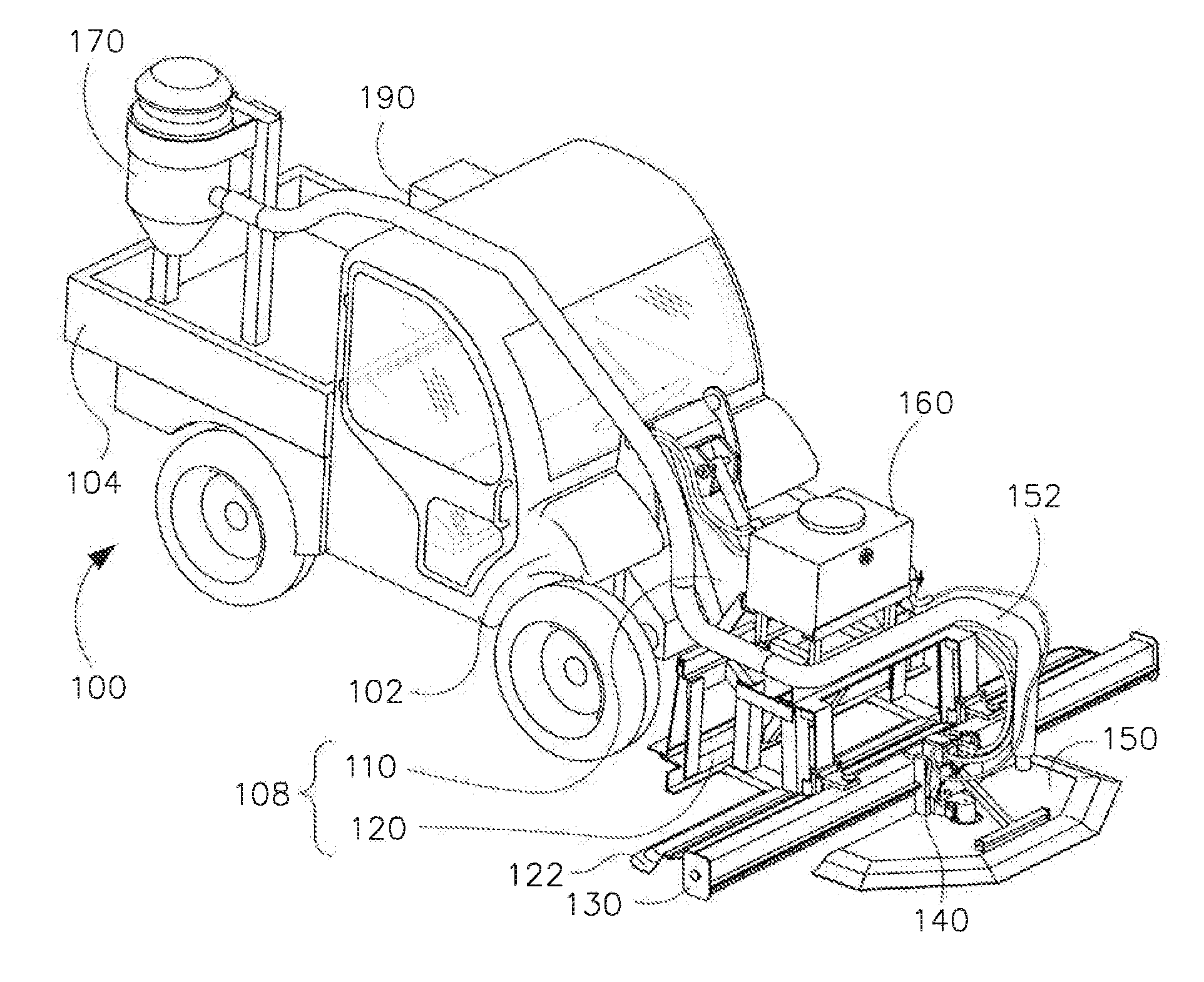
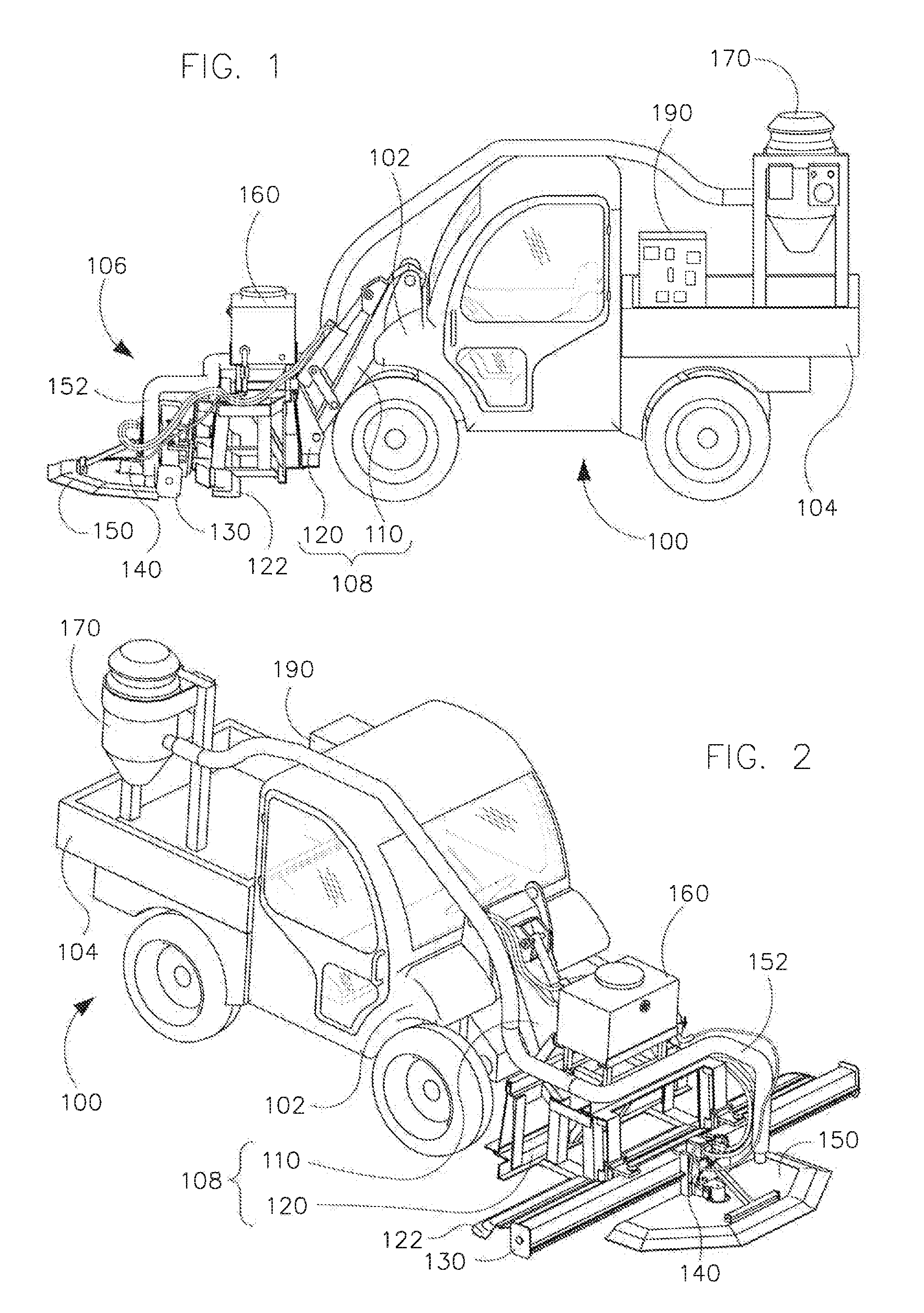
[0018]In various exemplary embodiments according to this invention, a guide rail and an associated hydraulic concrete saw head and saw blade are mounted onto a small utility vehicle that can easily move the saw head and guide rails along a hard-surfaced pathway from one trip hazard to another. In various exemplary embodiments, the utility vehicle has a hydraulic power system that is sufficiently powerful that it can drive the hydraulic saw head without overheating during normal use on a typical summer day. In various exemplary embodiments, a support structure is provided between the utility vehicle and the guide rails, which are mounted to the controllable support structure.
[0019]In various exemplary embodiments, the support structure allows the utility vehicle to picked up the guide rails and saw head, easily moved them from a current location to a next location and place them so they are ready to cut off the offending offset at that next location. In various exemplary embodiments, the support structure automatically locates the guide rails and the saw head relative to a lower slab of the hard-surfaced pathway so that the location and angle of the saw blade are appropriate to create one or more appropriate transition surfaces between the offset portions of the hard-surfaced pathway.
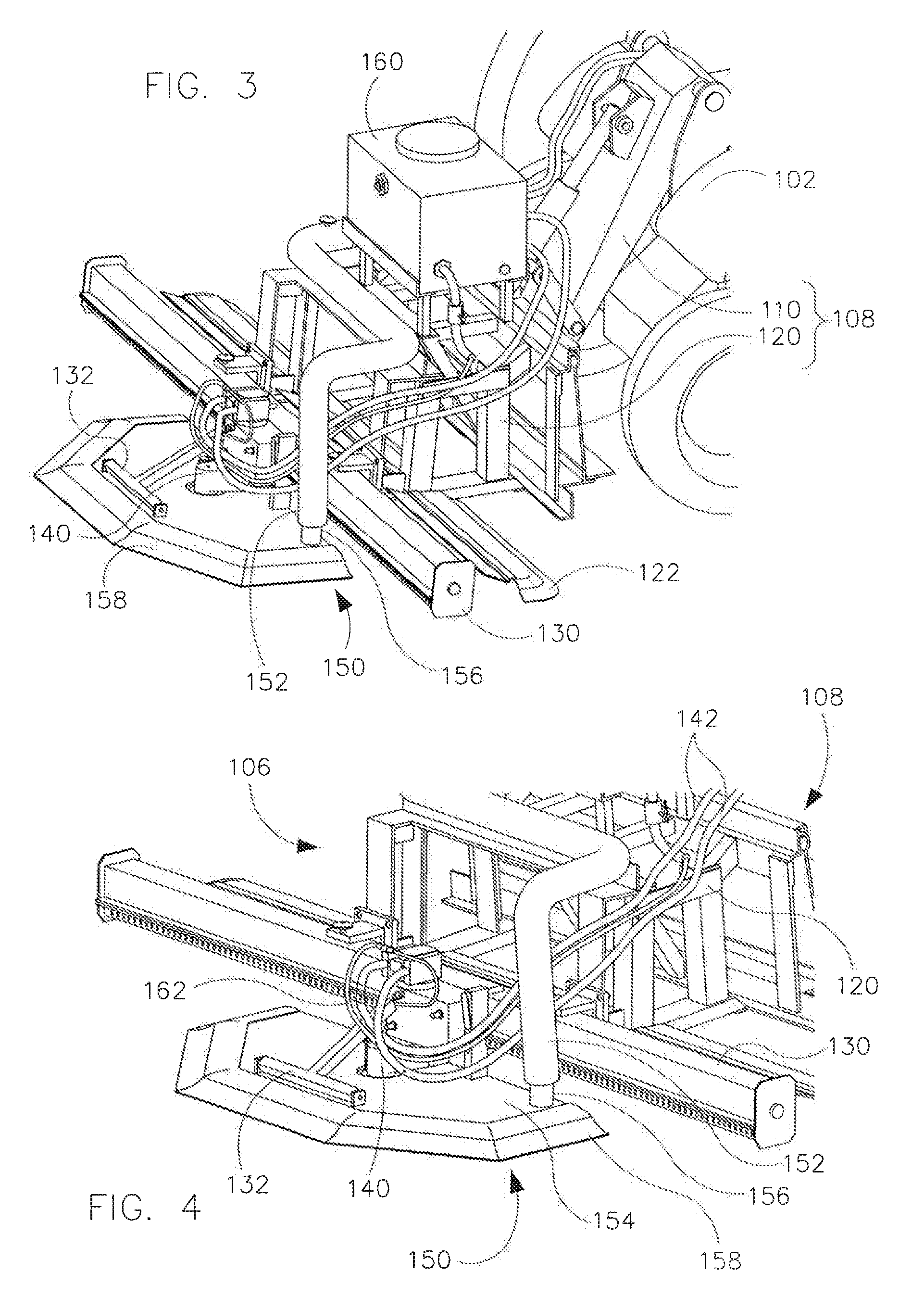
[0022]The hydraulic power system is turned on to drive the saw head and rotate the saw blade. An arm of the saw head is then rotated to move the saw blade from a disengaged position to an appropriate cutting position. The saw head and blade are then moved along the guide rails to cut into the upwardly offset portion of the hard-surfaced pathway. The cut is begun at one lateral edge of that upper portion at the full depth of the cut, i.e., the cut extends at the correct angle from the surface of the upper portion to the surface of the lower portion, such that the saw blade removes the trip hazard, in a single pass. The saw head and blade moved, either by hand or by another motor, along the guide rails to the other lateral edge of the upper portion, As a result, in one pass, the trip hazard is removed and an appropriately-sloped transition surface is created between the upper and lower portions of the hard-surfaced pathway.

Problems solved by technology

However, this proved too expensive and time consuming, especially if the portions of the hard-surfaced pathway were otherwise structurally sound and thus otherwise did not require replacement.

Method used


Image

  • Systems, machines, devices and methods for efficiently removing sidewalk trip hazards
  • Systems, machines, devices and methods for efficiently removing sidewalk trip hazards
  • Systems, machines, devices and methods for efficiently removing sidewalk trip hazards

Examples


Embodiment Construction

[0007]One early solution to these problems, as shown in U.S. Pat. No. 5,116,162, was to grind away only the offending offset. However, this was time consuming, not significantly less expensive, and created substantial amounts of concrete dust, which is a health hazard itself. In response to these problems in grinding away the offending offset, as shown in U.S. Pat. No. 6,863,062, a further solution was to cut away the offending offset using a rotating concrete saw and blade, by plunging the blade into the top surface of the concrete slab. This solution avoided creating as much concrete dust, and the actual concrete cutting is less time consuming than grinding away the offending offset. However, moving the concrete cutting device disclosed in the 062 patent from one trip hazard location to the next and setting up that concrete cutting device at each trip hazard location was itself time consuming and complicated.

[0008]Other solutions directed to concrete cutting, such as those shown i...


PUM

PropertyMeasurementUnit
angleaaaaaaaaaa
widthaaaaaaaaaa
flow rateaaaaaaaaaa

Abstract

A trip hazard removing apparatus includes a saw head and blade connected to guide rail(s), which are connected to a support structure, which is connected to lift arm(s) of a vehicle. The vehicle moves the trip hazard removing apparatus between trip hazards occurring between upper and lower slabs of a sidewalk, placing it on the lower slab adjacent to and in contact with a trip hazard, and lifting it after removing the trip hazard. A trip hazard engaging mechanism automatically locates the saw blade's position and angle relative to and above the upper slab to create appropriate transition surface(s) between the upper and lower slabs as it cuts off the trip hazard. The guide rail(s) allow placing the saw blade's facing the sidewalk's side surface. The saw head and blade are moved along the guide rail(s) across the upper slab and through the side surfaces to remove the trip hazard.

Description

[0001]This application claims priority to U.S. Provisional Application 61 / 301,070 filed Feb. 3, 2010, and U.S. Provisional Application 61 / 233,384 filed Aug. 12, 2009, each of which is incorporated herein by reference in its entirety.BACKGROUND[0002]1. Field of the Invention[0003]This invention is directed to efficiently removing trip hazards from sidewalks and other non-roadway hard-surfaced paths.[0004]2. Related Art[0005]The Americans with Disabilities Act (ADA) requires anyone responsible for a sidewalk or other hard-surfaced pathway that is commonly used by pedestrians to eliminate trip hazards, which is the term used to describe an offset between adjacent portions of the pathway that is more than ¼ inch in height. Typically, the material used for such hard-surfaced pathways is either concrete or asphalt.[0006]Accordingly, a significant market has developed in removing these trip hazards from sidewalks, bike paths and other hard-surfaced pedestrian pathways, and especially concr...

Claims


Application Information

Patent Timeline
Patent Type & Authority Applications(United States)
IPC IPC(8): E01C23/088E01C23/00E01C23/06
CPCB28D1/045B28D7/02E01C23/09E01C2301/50B28D1/044E01C23/0885
Inventor BOLLINGER, KEVIN
Owner BOLLINGER KEVIN
Why Eureka
Try Eureka