Retroreflective member producing iridescent reflected light

a technology of iridescent reflected light and retroreflective members, which is applied in the direction of instruments, roads, constructions, etc., can solve the problems of difficult to produce a desired design, difficult to display clear and desired colors under diffused light conditions, etc., and achieve enhanced visibility, improved safety, and improved visibility.

Active Publication Date: 2011-02-17
MARUJIN
View PDF7 Cites 13 Cited by
  • Summary
  • Abstract
  • Description
  • Claims
  • Application Information

AI Technical Summary

Benefits of technology

[0060]A retroreflective member of the present invention has a light-transmissive interference layer, and the optical layer thickness of the interference layer is set to 100 to 600 nm. According to the present invention, highly visible iridescent reflected light can be assuredly produced, and consequently, the visibility can be improved further.
[0061]More specifically, it becomes possible to provide a retroreflective member that can be converted to any design or shape, can show clear and desired colors under diffused light conditions, can exhibit retroreflective performance with improved safety under retroreflection conditions, and can enhanced visibility at nighttime by adding varying interference colors to the retroreflected light. Because the reflected light differs from reflected light produced by widely used general reflective members or light produced by road lamps on pedestrian walkways along roads, distant streetlights, and other non-reflective-member sources, the visibility to drivers can be improved.

Problems solved by technology

Although the reflected light can be colored by coloring the surface of the reflective member or by bonding a film or the like thereto, it is impossible to display clear and desired colors under diffused light conditions.
In addition, the thickness and texture (hardness) of the base member make it hard to produce a desired design.

Method used


Image

  • Retroreflective member producing iridescent reflected light
  • Retroreflective member producing iridescent reflected light
  • Retroreflective member producing iridescent reflected light

Examples


first embodiment

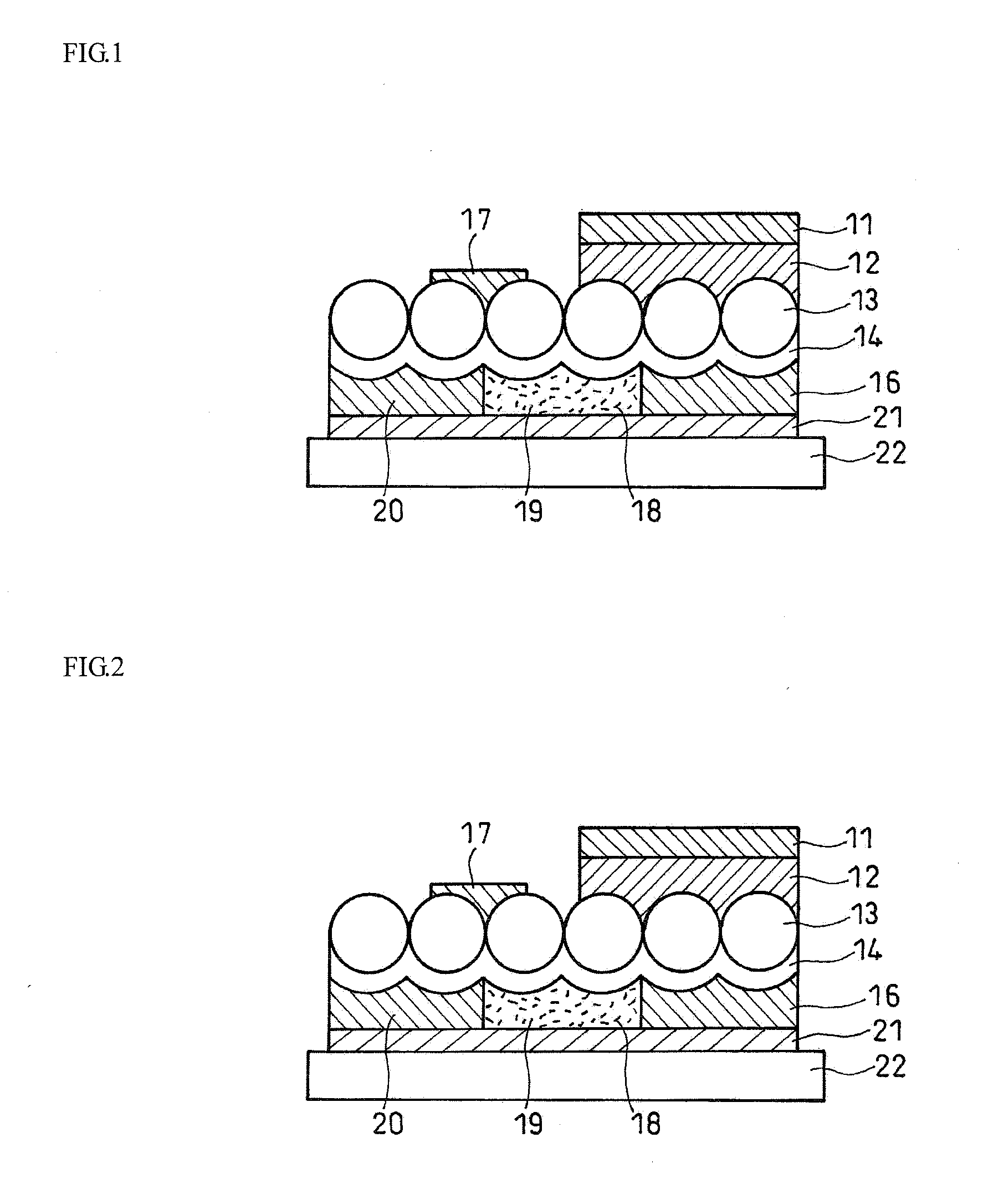
[0063]FIG. 1 is an enlarged sectional view showing the structure of a retroreflective member according to a first embodiment of the present invention. In FIG. 1 and other drawings, for the sake of convenience in illustration, just a portion of the retroreflective member extending in a planar direction is drawn such that it has an uninterrupted regular arrangement of glass beads and has layers each with an even thickness in the direction in which the planar layer extends. The dimensions of the glass beads and the thickness of each layer are not always illustrated at an accurate ratio with respect to the thickness of a different layer, and the thickness is sometimes increased or decreased for the sake of description.

[0064]In FIG. 1, the retroreflective member has a layer structure that includes a base layer 11, a covering layer 12, glass beads (transparent microscopic beads) 13, a multilayer interference film (interference layer) 14, a colored resin layer (colored layer) 16, and an ad...

second embodiment

[0079]The basic structure in FIG. 2 is the same as that shown in FIG. 1, but it is also preferable to use a single-layer interference film 15, as means for reducing the cost and loss rate in comparison with the multilayer interference film 14.

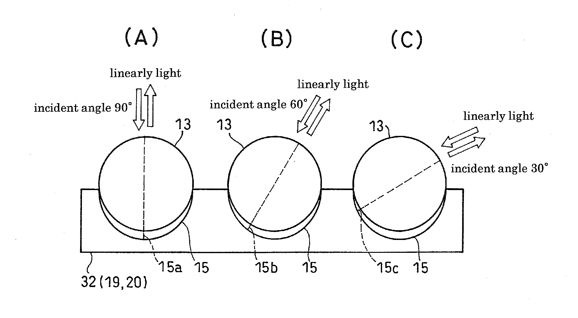
[0080]The single-layer interference film (interference layer) 15 is a single layer of a high-refractive-index metal compound or a low-refractive-index metal compound described in claim 4 (or a metal compound described in claim 12). This interference film 15 is a reflective layer using interference, its thickness can change, and an interference color can be obtained also from interference with the metal compound. Since the metal compound has such properties that the evaporated compound is readily deposited on a projected part of the deposition face and does not easily drip, it can foam the single-layer interference film 15 having varying thickness by depositing it not on a flat face such as film but on glass bead sheeting (the base layer 11, the...

third embodiment

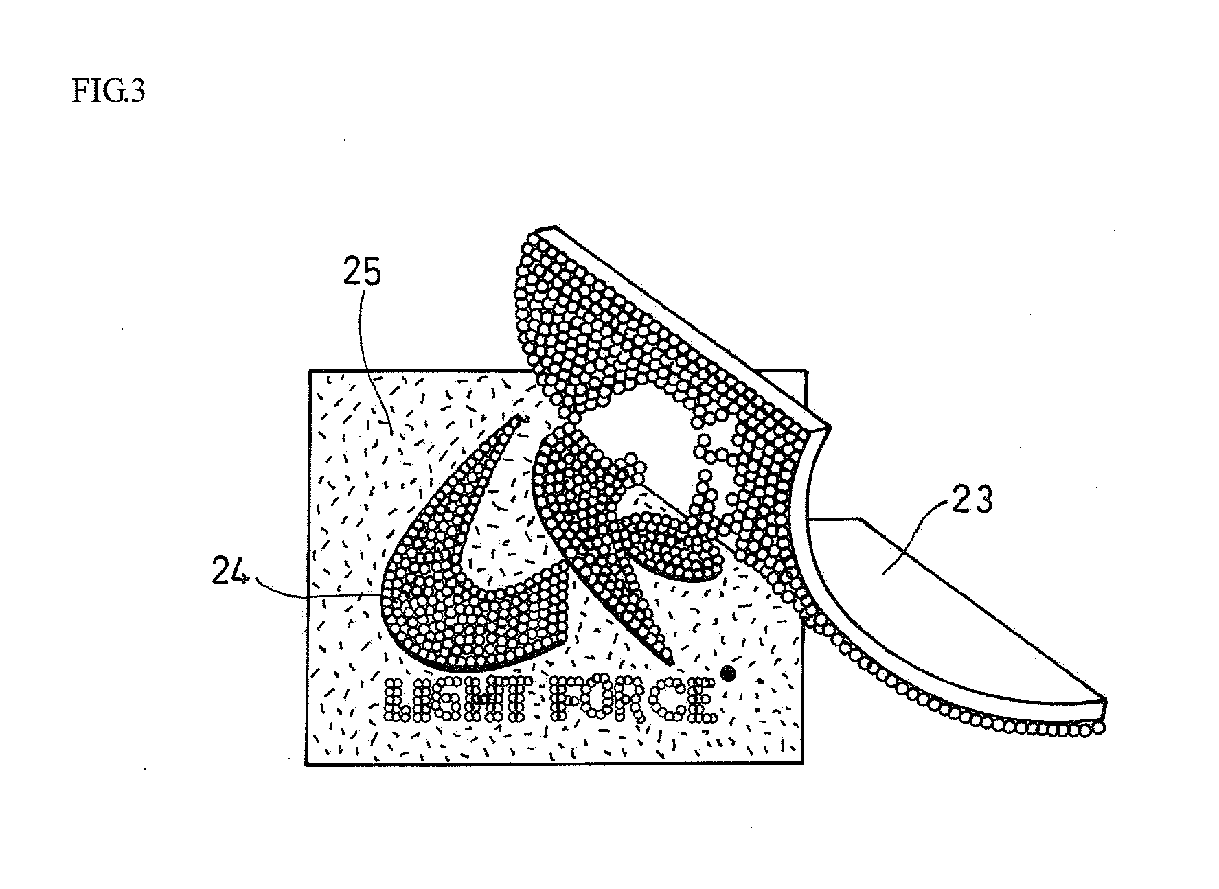
[0085]FIG. 3 is a view showing the structure of an embodiment using a retroreflective member according to the present invention. A base member 23 includes the base layer 11, the covering layer 12, and the glass beads 13. The reflective colored resin layer 19, the colored resin layer 16, the transparent resin layer 20, and the adhesive resin layer 21 are silk-screen-printed in a desired design and shape on a part of the base member 23. The face of the adhesive resin layer 21 is stuck to a target surface 25, and the base member 23 is peeled off. Then, a transfer image 24, including the glass beads 13, the reflective colored resin layer 19, the colored resin layer 16, the transparent resin layer 20, and the adhesive resin layer 21, silk-screen-printed in the desired design and shape, is stuck to the target surface 25.

[0086]When the reflective colored resin layer 19 and the colored resin layer 16 have unrelated colors or related colors, they can be used to produce a visually recognizabl...


PUM

PropertyMeasurementUnit
thicknessaaaaaaaaaa
thicknessaaaaaaaaaa
thicknessaaaaaaaaaa

Abstract

An object of the present invention is to provide a retroreflective member that can improve the visibility further. The retroreflective member includes a reflective layer and transparent microscopic beads 13. The retroreflective member gives a phase difference corresponding to a visible light wavelength to at least a part of incident light and recombines, emphasizes a light component having the visible light wavelength by interference, and returns coherent light having a visible light wavelength depending on the incident angle in the traveling direction of the incident light. The reflective layer includes a light-transmissive interference layer 14, and the interference layer 14 each has an optical layer thickness of 100 to 600 nm so as to generate an interference color having a visible light wavelength depending on the incident angle of light.

Description

TECHNICAL FIELD[0001]The present invention relates to retroreflective members, and more specifically, to improvements of retroreflective members using retroreflected light and interference colors of a metal compound.BACKGROUND ART[0002]Retroreflective members that exhibit clear and desired colors under diffused light conditions and that exhibit sufficient reflected luminance under retroreflection conditions have been proposed (Patent Documents 1 to 3, for instance).[0003]Reflected light from conventional retroreflective members cannot be colored directly, and the reflected light has just a single color. Although the reflected light can be colored by coloring the surface of the reflective member or by bonding a film or the like thereto, it is impossible to display clear and desired colors under diffused light conditions. In addition, the thickness and texture (hardness) of the base member make it hard to produce a desired design.Patent Document 1: Japanese Patent No. 3432507 (Color r...

Claims


Application Information

Patent Timeline
Patent Type & Authority Applications(United States)
IPC IPC(8): G02B5/128B32B7/02E01F9/619
CPCG02B5/285G02B5/128
Inventor KOBAYASHI, HIRONORIAMEMORI, SHOJIRO
Owner MARUJIN
Why Eureka
Try Eureka