
Method and device for near-field dual-wave modality imaging

a dual-wave modality and imaging technology, applied in the field of methods and devices for nearfield imaging of a region of interest, can solve the problems of inability to detect high sensitivity, advanced radio-chemistry expertise, and the need for cyclotron facilities,

Inactive Publication Date: 2011-02-17
HELMHOLTZ ZENT MUNCHEN DEUTES FORSCHUNGSZENT FUR GESUNDHEIT & UMWELT
View PDF55 Cites 62 Cited by
  • Summary
  • Abstract
  • Description
  • Claims
  • Application Information

AI Technical Summary

Problems solved by technology

The major disadvantage of those methods is the ionizing radiation they em ploy and the need for cyclotron facilities, advanced radio-chemistry expertise and the radio-decay of the probes used, which is inappropriate for storing agents or for longitudinal monitoring studies.
Generally, MRI probes need cannot be detected with high sensitivity, which compromises the range of applications of this approach.
Thus, placement of a certain part of the sample in the near-field is considered as an unwanted effect that is not imaged with the conventional method.
Despite some promising characteristics of TAT, it has not become a mainstream imaging approach due to several shortcomings.
First, operation at the far-field imposes significant losses due to the reflection of the radiated energy.
Since a significant part of the energy is lost on its way to the object, thermoacoustic signal generation becomes inefficient, which significantly compromises the signal-to-noise ratio at practical and safe power levels.
Second, existing thermoacoustic tomography methods utilize irradiation of the object by using narrow-band microwave radiation, i.e., electromagnetic energy deposition in the far-field.
Conversely, significantly reducing the pulse duration, to achieve high spatial resolution leads to small or undetectable thermoacoustic signal levels.
This, in turn, requires dedicated and extremely expensive pulse generation and amplification equipment and may also impose safety concerns in regard to the instrumentation used.
Overall the low SNR, usually obtained in the existing methods, hinders their practical implementation in the field.
The optical techniques are thus considered for molecular sensing, but they generally suffer from low penetration depth in tissues and limited resolution when imaging deep in tissue, which may limit clinical applications to tissue surface imaging and invasive or endoscopic applications.

Method used


Image

  • Method and device for near-field dual-wave modality imaging
  • Method and device for near-field dual-wave modality imaging
  • Method and device for near-field dual-wave modality imaging

Examples


Embodiment Construction

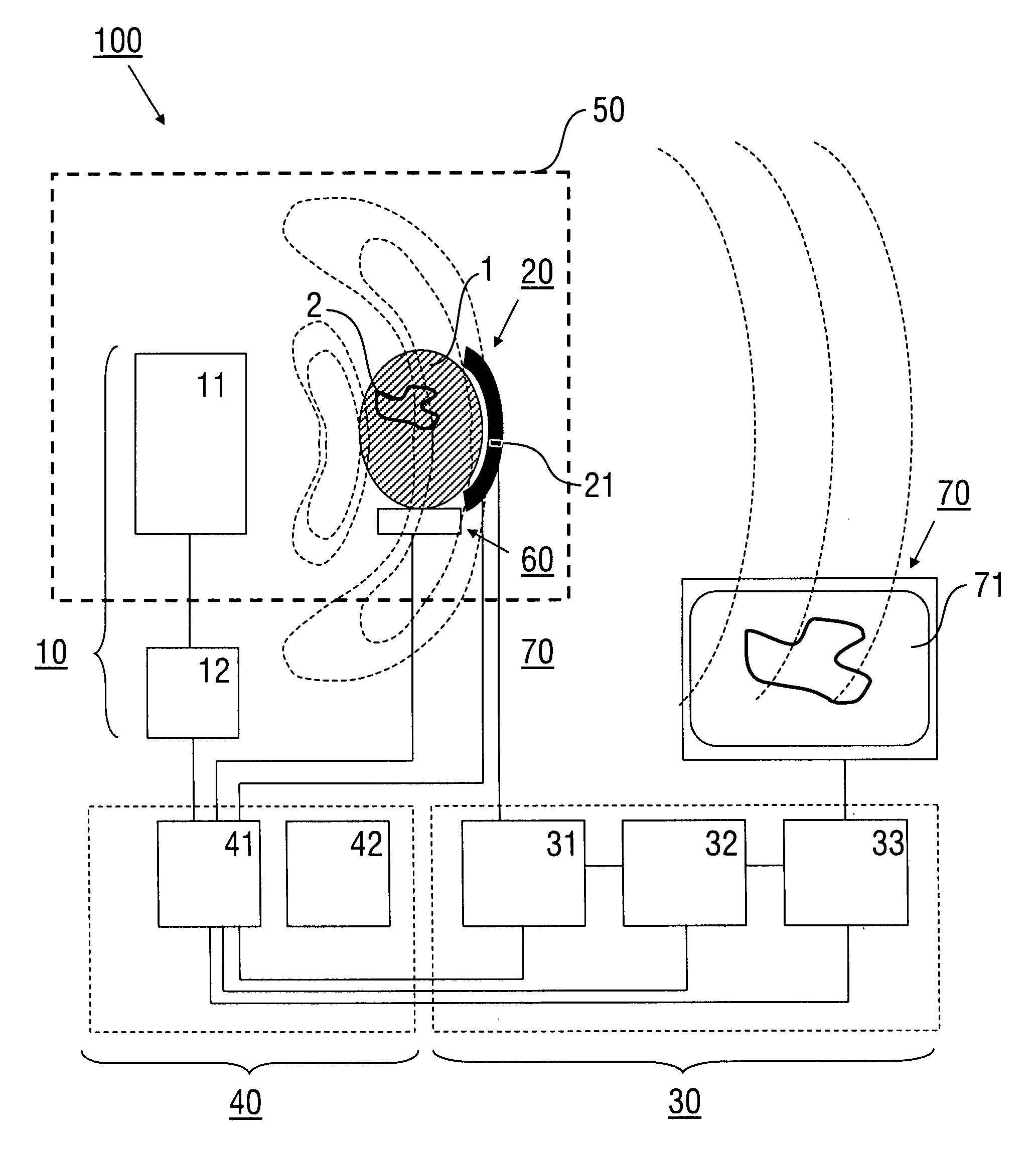
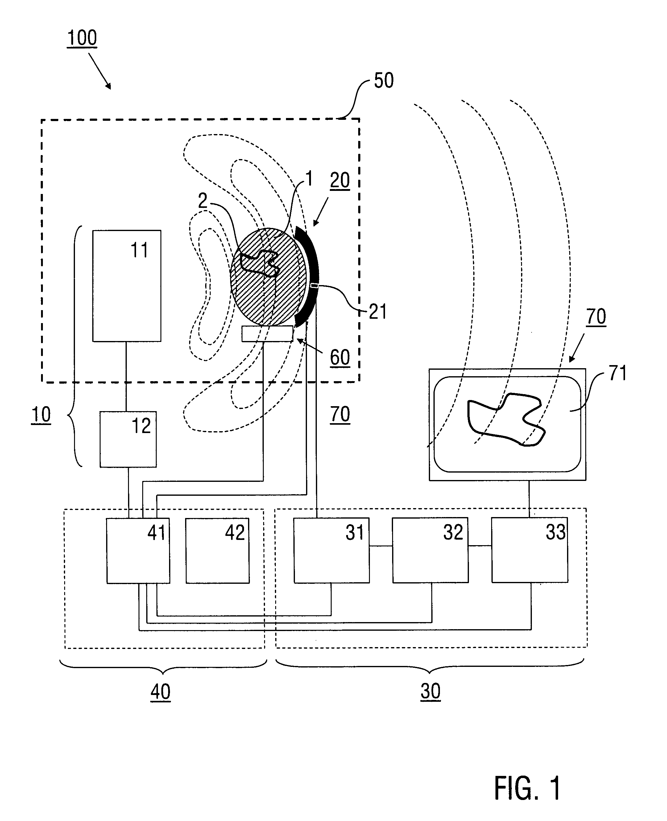
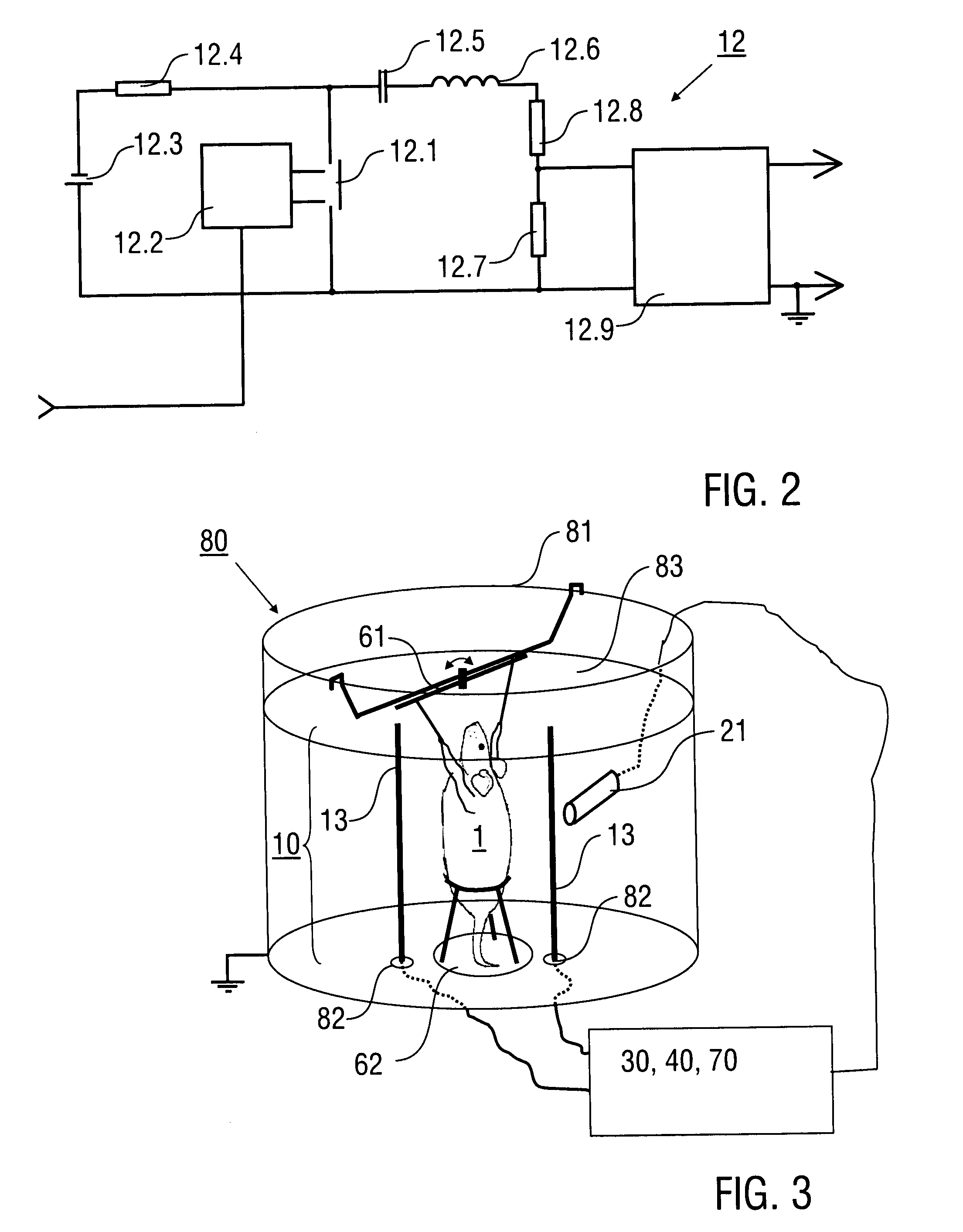
[0021]We provide a method of near-field imaging of a region of interest (ROI) in an object, whereas the ROI is subjected to an input of near-field electromagnetic energy in the radiofrequency range, a mechanical wave response is detected in response to the near-field electromagnetic energy input in the ROI, and signals representing the detected mechanical wave response are converted into image data representing an image of the ROI. The method relies on near-field exposure of the object or tissue to electromagnetic sources of safe energies and allows image formation based on the mathematical treatment of detected data generated as readings of pressure waves generated by near-field energy absorption from tissue elements. Contrary to conventional techniques, the ROI is a sample region which is located in the near-field. The ROI located in the near-field is imaged. We found that utilizing the near-field is not limited due to the heterogeneous structure thereof, but rather associated wit...


PUM


Abstract

A method of near-field imaging of a region of interest includes emitting an input of near-field electromagnetic radiofrequency energy from a near-field source device into the region of interest, detecting a mechanical wave response generated in the region of interest in response to the near-field electromagnetic energy input using a detector device, and providing image data representing an image of the region of interest based on the mechanical wave response.

Description

RELATED APPLICATIONS[0001]This is a §371 of International Application No. PCT / EP2009 / 001137, with an international filing date of Feb. 18, 2009 (WO 2009 / 103502 A1, published Aug. 27, 2009), which is based on U.S. Patent Application No. 61 / 066,187, filed Feb. 19, 2008, and European Patent Application No. 08006528.7, filed Mar. 31, 2008, the subject matter of which is incorporated by reference.TECHNICAL FIELD[0002]This disclosure relates to a method and a device for near-field imaging of a region of interest using near-field electromagnetic waves. The method, termed Near-field Radiofrequency Tomography (NRT), and the device are capable of producing tomographic images of, e.g., anatomical, functional and molecular characteristics of biological objects, like biological tissues, or non-biological objects.BACKGROUND[0003]Medical imaging has been used for more than a century to non-invasively assess tissue pathology. The progress of many diseases is associated with conformational, physiolo...

Claims


Application Information

Patent Timeline
IPC IPC(8): A61B5/05G06K9/00G01S13/00
CPCA61B5/0095A61B5/05A61B2503/40A61B8/08G01N2021/1787A61B8/00
Inventor RAZANSKY, DANIELNTZIACHRISTOS, VASILIS
Owner HELMHOLTZ ZENT MUNCHEN DEUTES FORSCHUNGSZENT FUR GESUNDHEIT & UMWELT
Learn More