Signal transfer point front end processor

a signal transfer point and front end technology, applied in the field of packet transmission, can solve the problems of limited inherent security capabilities, signal transfer points vulnerable to viruses, various network vulnerabilities, etc., and achieve the effect of higher levels of the ss7 protocol stack

Inactive Publication Date: 2011-02-17
AT&T MOBILITY II LLC
View PDF9 Cites 13 Cited by
  • Summary
  • Abstract
  • Description
  • Claims
  • Application Information

AI Technical Summary

Benefits of technology

[0010]As described hereinbelow, the STP-FEP of the present invention provides advantages...

Problems solved by technology

Signal Transfer Points are essentially network routers which do not have sophisticated packet-filtering processors and thus hav...

Method used


Image

  • Signal transfer point front end processor
  • Signal transfer point front end processor
  • Signal transfer point front end processor

Examples


Embodiment Construction

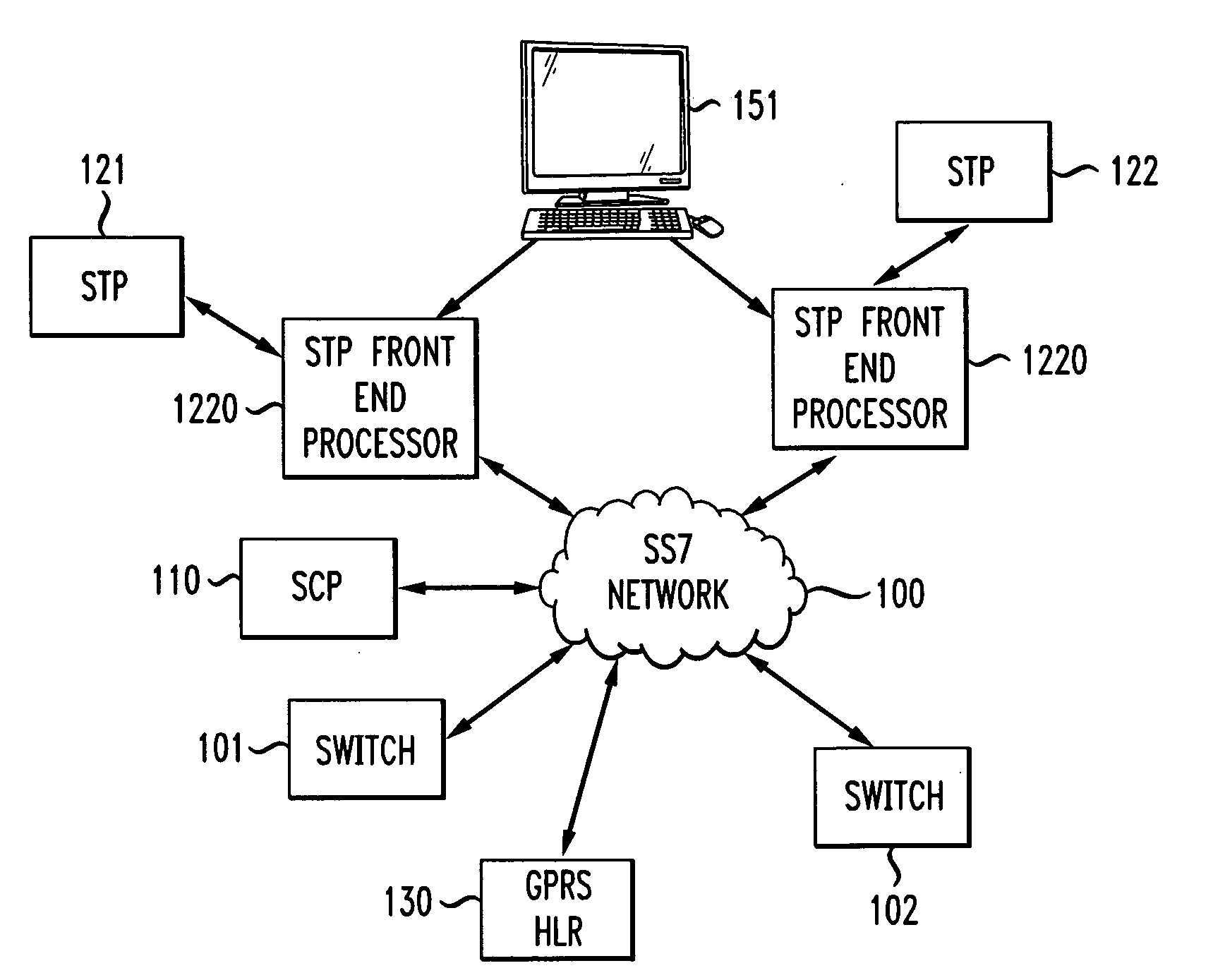
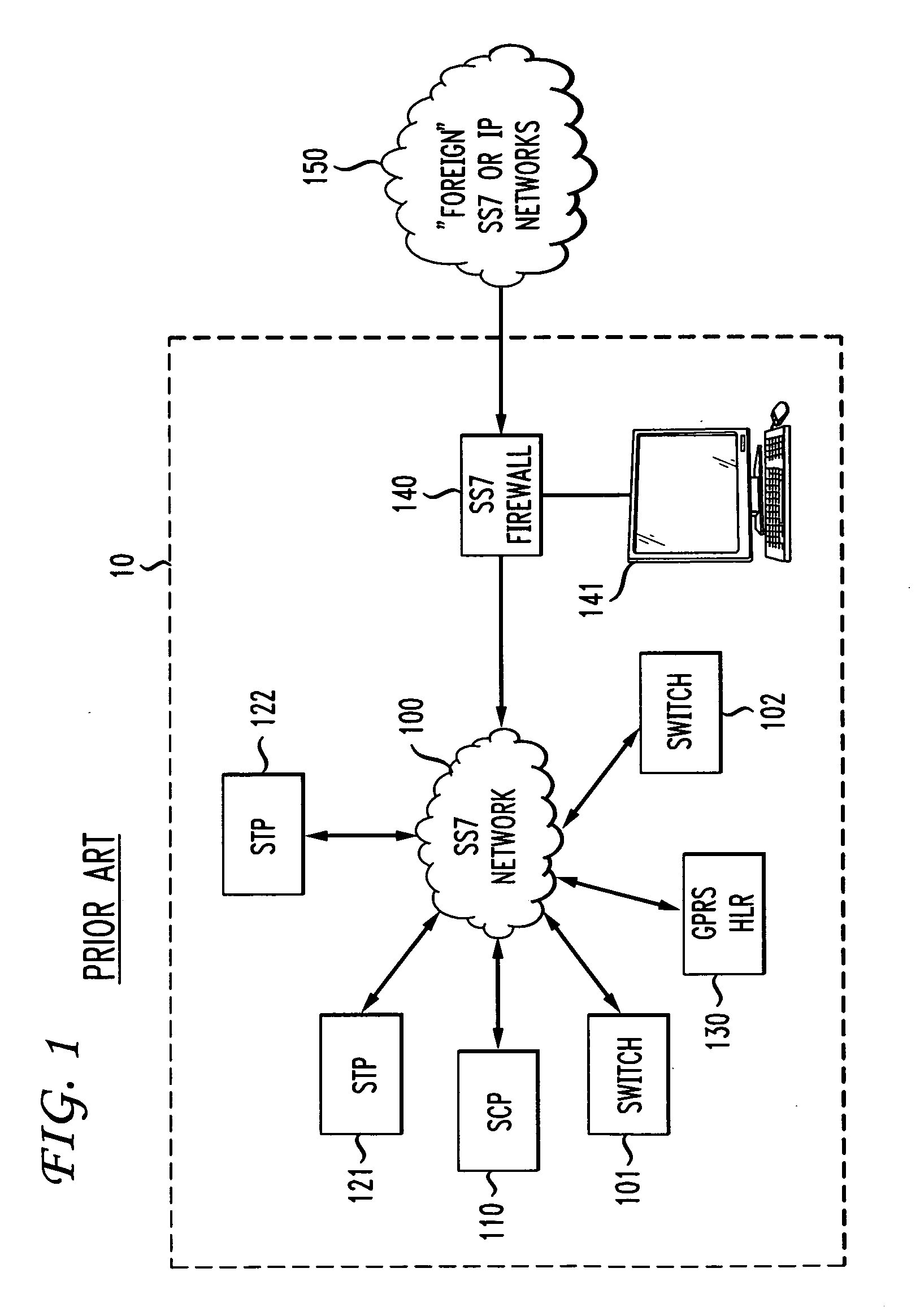
[0018]FIG. 1 shows elements of a telecommunications network 10—which is illustratively a wireless communication network—implementing the prior art approach of implementing SS7 security using a firewall.

[0019]Network 10 includes a plurality of switches, such as switches 101 and 102, which set up and support circuits between user terminals, such as cellular telephones communicating with the switches via cellular base stations, neither of which are shown. Also not shown is the network infrastructure of trunks and other links over which those circuits are established. What is shown, however, is SS7 network 100 over which switches such as switches 101 and 102 communicate between and among themselves and other network elements using the packet-based, SS7 protocol in order to set up and tear down calls and perform other internal network tasks. Entities that communicate across and within an SS7 network are referred to as “signaling points.” Signaling points shown in FIG. 1 include Signal Co...


PUM


Abstract

In an SS7 network, each of a plurality of Signal Transfer Points is fronted by a front-end processor (STP-FEP) that has a network presence. The STP-FEP implements at least the MTP2 layer of the SS7 protocol stack and implements security rules at the MTP2 and MTP3 layers.

Description

BACKGROUND [0001]The present invention relates to packet transmission and, more particularly, to the filtering of packets transmitted over SS7 and other packet transmission networks.[0002]At each signaling point of a Signaling System 7 (SS7) network is some type of computer element that has a network card connecting the point to the network. These network cards are designed to operate in accordance with the SS7 protocol, which defines standards for communication between signaling points.[0003]Among those signaling points are Signal Transfer Points (STPs). These are switching elements of SS7 networks that route SS7 packets between network endpoints. Signal Transfer Points perform signal routing, packet integrity controls and routing analysis of SS7 packets.[0004]Signal Transfer Points are essentially network routers which do not have sophisticated packet-filtering processors and thus have limited inherent security capabilities. This makes Signal Transfer Points vulnerable to viruses ...

Claims


Application Information

Patent Timeline
IPC IPC(8): G06F21/00
CPCH04L63/0227H04Q3/0025
Inventor MARIA, ARTURO
Owner AT&T MOBILITY II LLC
Why Eureka
Try Eureka