Propulsion mechanism employing conversion of rotary motion into a unidirectional linear force

a technology of unidirectional linear force and rotational mechanism, which is applied in the direction of motors, belts/chains/gearings, and belts. it can solve the problems of reducing the torque effect of the rotational mechanism and the entire device, and achieves the effect of reducing the reciprocating counter force, minimizing wear, and easy production

Inactive Publication Date: 2011-02-24
SMITH DAVID S
View PDF12 Cites 5 Cited by
  • Summary
  • Abstract
  • Description
  • Claims
  • Application Information

AI Technical Summary

Benefits of technology

[0008]The present invention is accordingly directed toward an improved mechanism for converting centrifugal forces produced during rotary motion into a net linear force. This mechanism which is relatively simple, extremely compact and easily produced, with a very small number of moving parts, is reversible and minimizes the wear produced on the components. This mechanism has also been produced in a number of prototypes and has functioned repeatedly and dependably for extended periods of time.
[0009]The present invention provides a rotational mechanism preferably supported on one or more rails within a vehicle so that the unbalanced linear motion of the rotational mechanism produces reciprocating translation of the mechanism along the rails. The sliding mounting reduces reciprocating counter force within the device thereby dampening backward oscillatory motion, allowing force to be produced in only one direction. The impact of the rotational mechanism with a stop at one end of the rail will produce a momentum transfer and accordingly a linear unidirectional force will be imposed on the body supporting the mechanism.
[0011]The counter-rotating radial arms both come into the same angular disposition with respect to the central aspect twice during each full rotation of the arms at two points displaced 180° with respect to one another. The planetary weights on the two arms orbit so that they are in the same radial position with respect to their axes of rotation at the two locations of super-positions of the arms. At one point of super-position both orbiting gears are arrayed so that their centers of mass, or weighted areas, are at a maximum extension from the central axis of the rotating arms; that is the weighted portions lie along the axes of the respective radial arms in a direction away from the central axis. At the radially opposite 180° point of super-position of the two arms, the weighted portions are oriented toward the central axis. This arrangement can be viewed as an effective shifting of the centers of mass of the radial arms as they undergo rotation about their common axis. At their point of super-position where the weights are directed away from the central axis, the centrifugal forces exerted on the central axis are maximized and at the radial opposite super-position the forces are minimized. This produces a force vector in the direction of the maximum radius of the centers of mass, causing motion of the revolving mechanism toward one end of the rails where its slide mounting impacts a stop, transferring the linear momentum of the rotating mechanism to the underlying support vehicle. As the arms continue to rotate, a smaller force vector is produced in the opposite direction, causing retraction of the rotating mechanism along the rails to its initial position. The vectors are also reversible, causing the primary force to be rotated 180 degrees.

Problems solved by technology

The counter rotation of the arms and gears also nullifies the effect of torque within the rotational mechanism and entire device.

Method used


Image

  • Propulsion mechanism employing conversion of rotary motion into a unidirectional linear force
  • Propulsion mechanism employing conversion of rotary motion into a unidirectional linear force
  • Propulsion mechanism employing conversion of rotary motion into a unidirectional linear force

Examples


Embodiment Construction

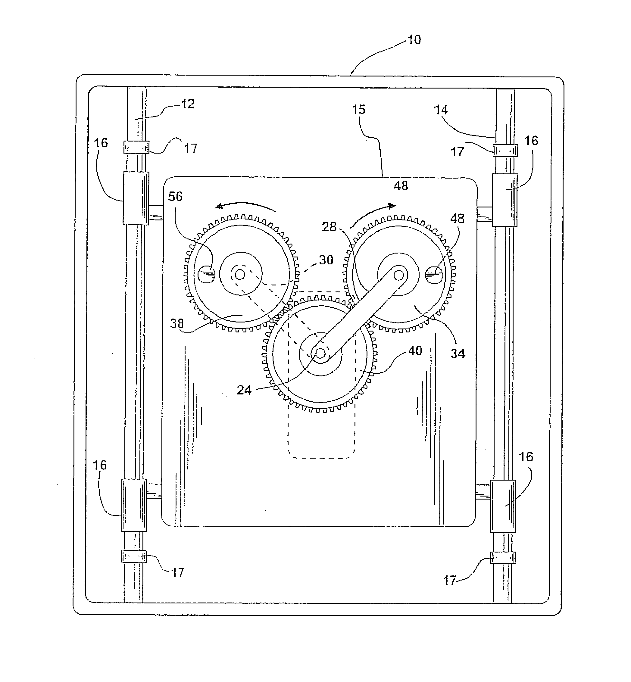
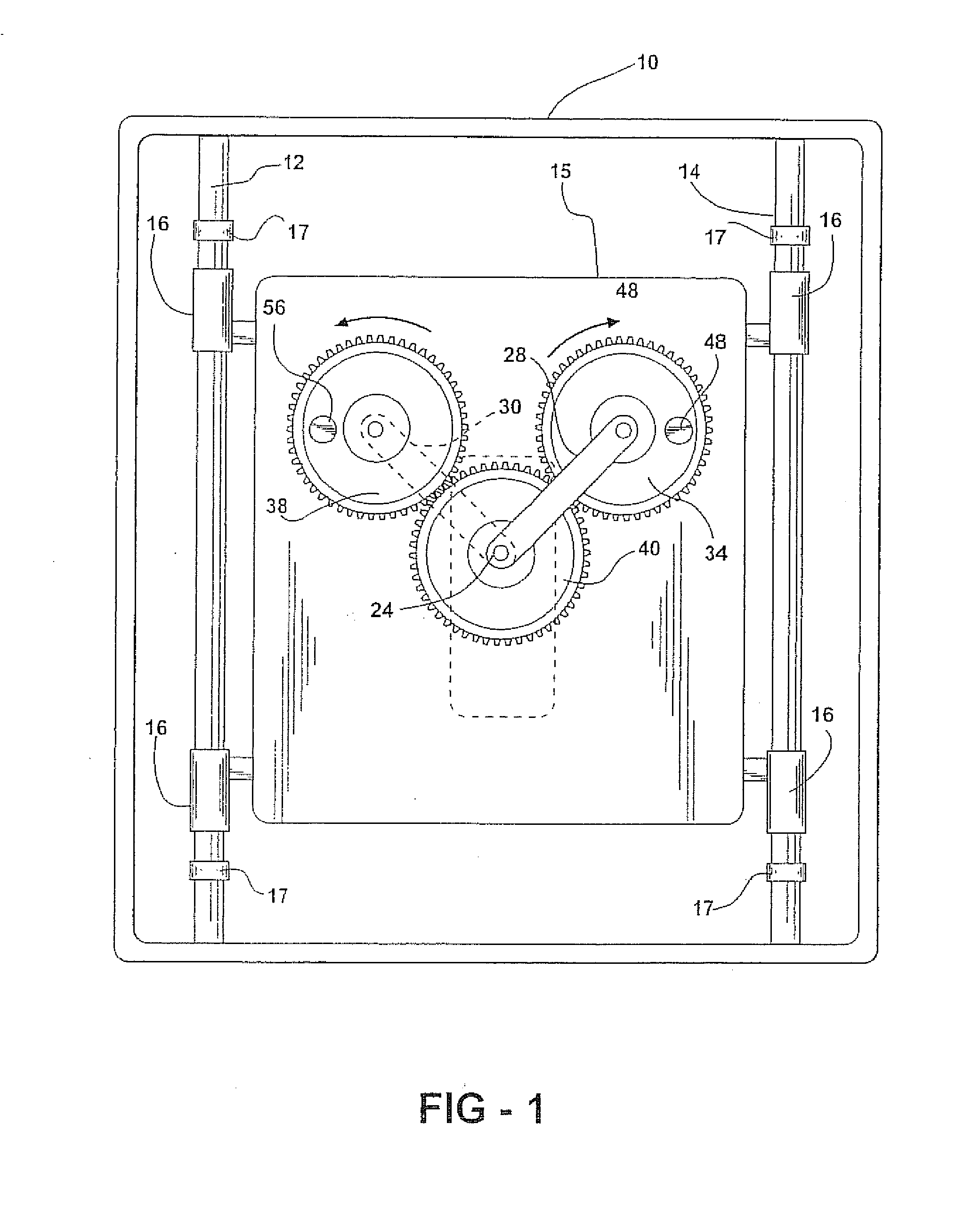
[0017]The device of the present invention is illustrated as being supported within a housing 10 having bottom, side walls and an open top. This housing may be attached to a movable vehicle or other structure or may comprise the vehicle itself. By way of example, the housing 10 could be floated on or suspended in (with top enclosed) a body of liquid such as water and the propulsive forces developed by the mechanism could propel the housing 10 over or through the liquid.

[0018]The side walls of the housing 10 support a pair of parallel spaced rails 12 and 14. A slide 15 is supported for sliding motion, back and forth, along the rails 12 and 14 by bushings 16 which engage the side rails. When the rails 12 and 14 are in a horizontal attitude, so that gravity forces do not bias the position of the slide along the rails, the slide 15 may freely move back and forth along the rails when propulsive forces are exerted in either direction parallel to the rails.

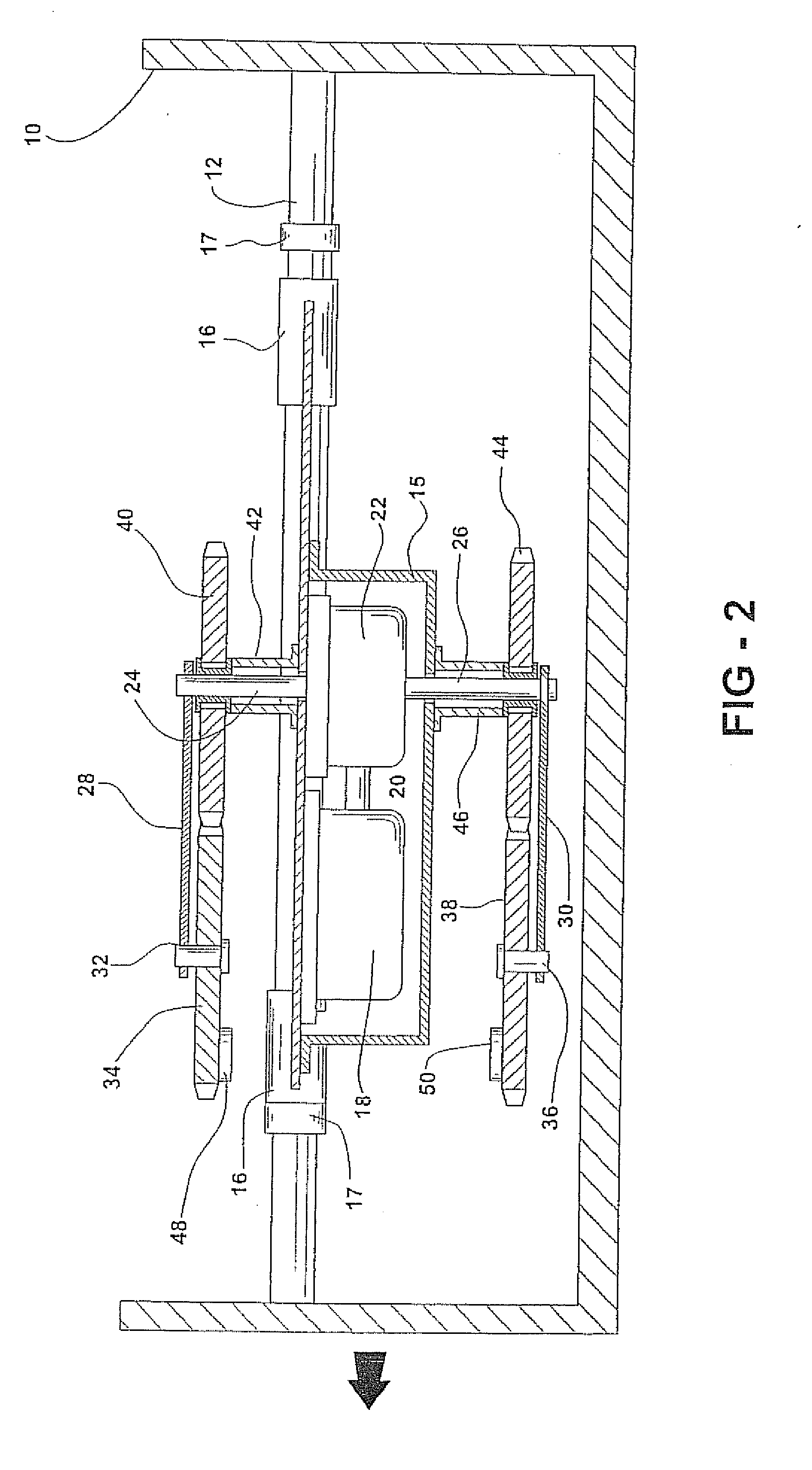
[0019]As shown in FIG. 2, the carr...


PUM


Abstract

A mechanism for converting rotary motion into a linear force employs a motor acting through a drive mechanism to rotate a pair of radial arms in counter-rotating directions, synchronously, about a central axis. A gear is rotatably supported about an axis normal to the plane of rotation of the arms, at the outer end of each arm. These two gears are weighted at points on their peripheries and the two gears are in mesh with identical, nonweighted fixed gears supported about the central axis, so that the weighted gears undergo one full rotation for each rotation of the arms. During each rotation of the arms, they experience two alignments, at two radially opposed positions. In one of the positions, the weighted segments are aligned so as to be positioned away from the central axis. At the other alignment position of the arms, the weighted segments are positioned close to the central axis. The unbalanced rotation of the arms and their weighted gears causes a centrifugal pulse in the direction of the most outward position of the rotating gears, moving the entire mechanism along a slide into abutment with a stop at one end of the mechanism to produce a net propulsive force. Rotation of the fixed gears 180 degrees reverses the thrust.

Description

CROSS-REFERENCE TO RELATED APPLICATIONS[0001]This application is a continuation-in-part of U.S. patent application Ser. No. 11 / 670,441 filed Feb. 2, 2007, which is a continuation of U.S. patent application Ser. No. 10 / 631,194 filed Jul. 31, 2003, now abandoned.BACKGROUND OF THE INVENTION[0002]This invention relates to a mechanism for converting the centrifugal forces produced by rotating masses to produce a single unbalanced propulsive force acting in one direction, so as to provide unidirectional linear motion to a supporting vehicle, and more particularly, to such a mechanism comprising a number of radial arms rotatable about a common axis which arms carry unbalanced weights at their ends which also rotate about axes parallel to the common axis and are aligned when the arms are super-imposed.PRIOR ART[0003]Devices to produce a propulsion force for vehicles such as automobiles and boats have been proposed which rotate masses about a central axis so as to produce centrifugal forces ...

Claims


Application Information

Patent Timeline
Patent Type & Authority Applications(United States)
IPC IPC(8): F16H21/18
CPCF03G3/00Y10T74/18344F05B2260/4031F03G7/10
Inventor SMITH, DAVID S.
Owner SMITH DAVID S
Why Eureka
Try Eureka