
Capacitive deionization device

a deionization device and capacitive technology, applied in the direction of electrolysis components, chemistry apparatus and processes, filtration, etc., can solve the problems of environmental damage, unsuitable hard water for washing, and significant reduction of the energy efficiency of the devi

Inactive Publication Date: 2011-02-24
SAMSUNG ELECTRONICS CO LTD
View PDF28 Cites 27 Cited by
  • Summary
  • Abstract
  • Description
  • Claims
  • Application Information

AI Technical Summary

Benefits of technology

[0016]In one embodiment, the at least one electrolyte solution may include a higher total concentra

Problems solved by technology

Unwanted and undesirable scaling easily occurs in a heat exchanger of a home appliance or an inner wall of a boiler when hard water containing high concentrations of hardness components is used therein, and thus energy efficiency of the device is significantly reduced due to the scaling.
In addition, hard water is unsuitable for washing due to the difficulty in producing lather.
However, such methods are inconvenient and cause environmental damage.
Furthermore, CDI devices may also remove harmful ions as well as hardness components when ions are adsorbed onto electrodes, and do not use a chemical to regenerate the electrodes and are thus have a relatively low environmental impact.
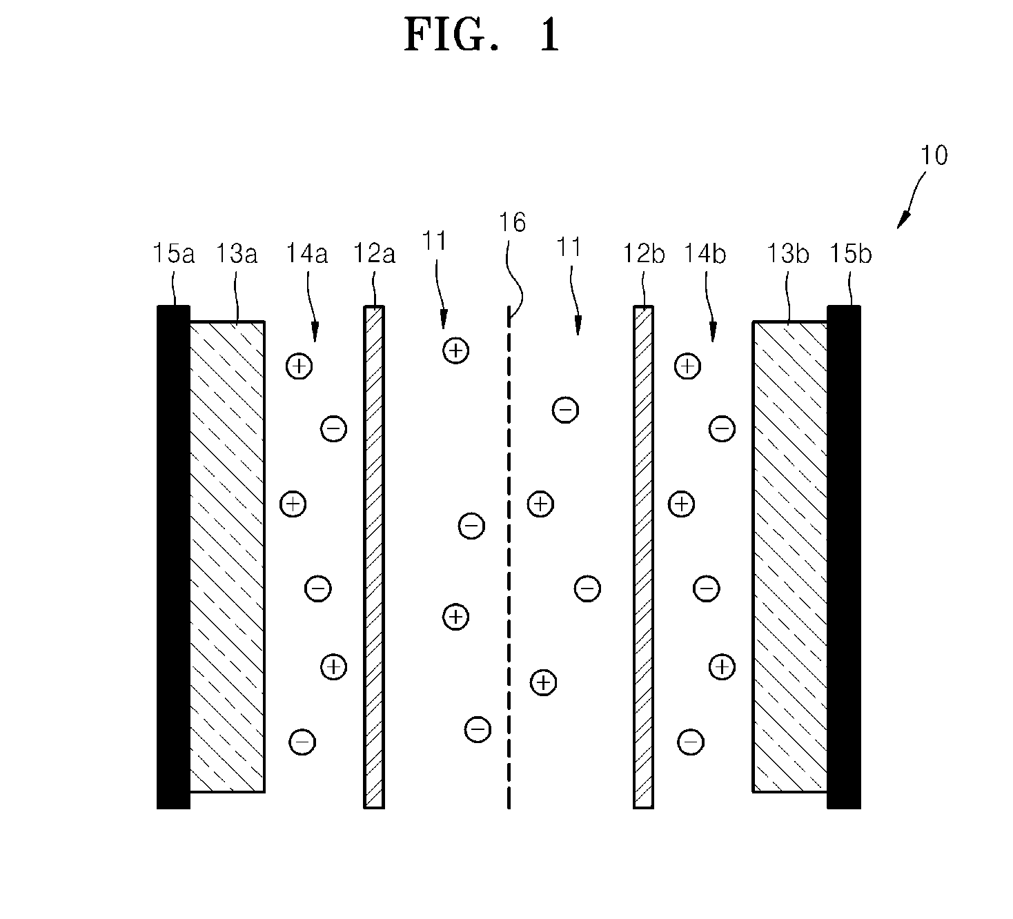
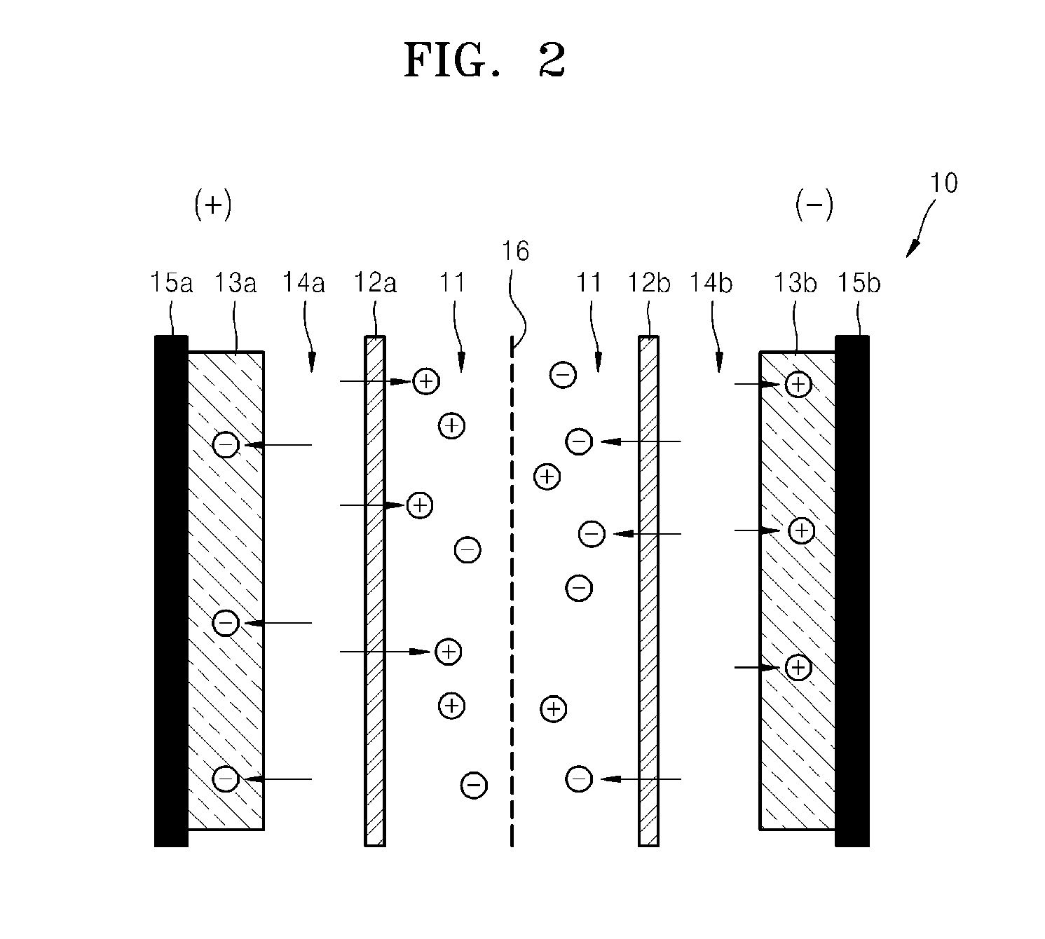
However, in general CDI devices, when a potential is applied to the electrodes, a large number of ions, i.e., co-ions, present in pores of the electrodes with the same polarity as the corresponding electrodes are expulsed into effluent water.
As such, it is difficult to control all the ions to be moved towards the corresponding electrode.
For this reason, CDI devices have a relatively low ion removal efficiency compared to the amount of applied charges.
However, when the charge-barrier CDI device is used to treat hard water including a hardness component of 300 ppm or less by weight, the concentration of ions in pores of the electrodes is relatively low, and the ion transfer rate in the pores is also low.
Thus, the capacitances of electrode materials may not be fully utilized during charging / discharging.
In addition, such general CDI devices or the charge-barrier CDI device exhibit a further lower ion removal efficiency when influent water to be treated contains ions that are unsuitable for generating capacitance of the electrode material.

Method used


Image

  • Capacitive deionization device
  • Capacitive deionization device
  • Capacitive deionization device

Examples


example 1

Manufacture of Electrode and Cell

1) Manufacture of Electrode

[0105]In this example, 40 g of activated carbon (having a specific surface area of 1300 m2 / g), 10 g of carbon black, and 4.17 g of an aqueous suspension of 60% by weight of PTFE, 130 g of propylene glycol, and 100 g of NH4HCO3 were put into a stirring vessel, kneaded, and then pressed to manufacture a porous electrode. The porous electrode was dried in an oven at 80° C. for 2 hours, at 120° C. for 1 hour, and at 200° C. for 1 hour to complete the manufacture of the porous electrode.

2) Manufacture of Cell

[0106]First, the porous electrode, which was dried as described above, was cut into 2 pieces, each having an area of 10 cm×10 cm (100 cm2), and a weight of each electrode was measured. Each of the porous electrodes had a weight of 5.9 g.

[0107]Second, the two electrodes were immersed in an electrolyte solution of 0.5M KCl aqueous solution in a vacuum.

[0108]Third, a cell was manufactured by sequentially stacking a current coll...

example 2

[0111]Electrodes and a cell were manufactured in the same manner as in Example 1, except that a 1 M KCl aqueous solution, instead of the 0.5 M KCl aqueous solution, was used as the electrolyte solution.

example 3

[0112]Electrodes and a cell were manufactured in the same manner as in Example 1, except that a 4 M KCl aqueous solution, instead of 0.5 M KCl aqueous solution, was used as the electrolyte solution.


PUM

PropertyMeasurementUnit
Timeaaaaaaaaaa
Electrical conductivityaaaaaaaaaa

Abstract

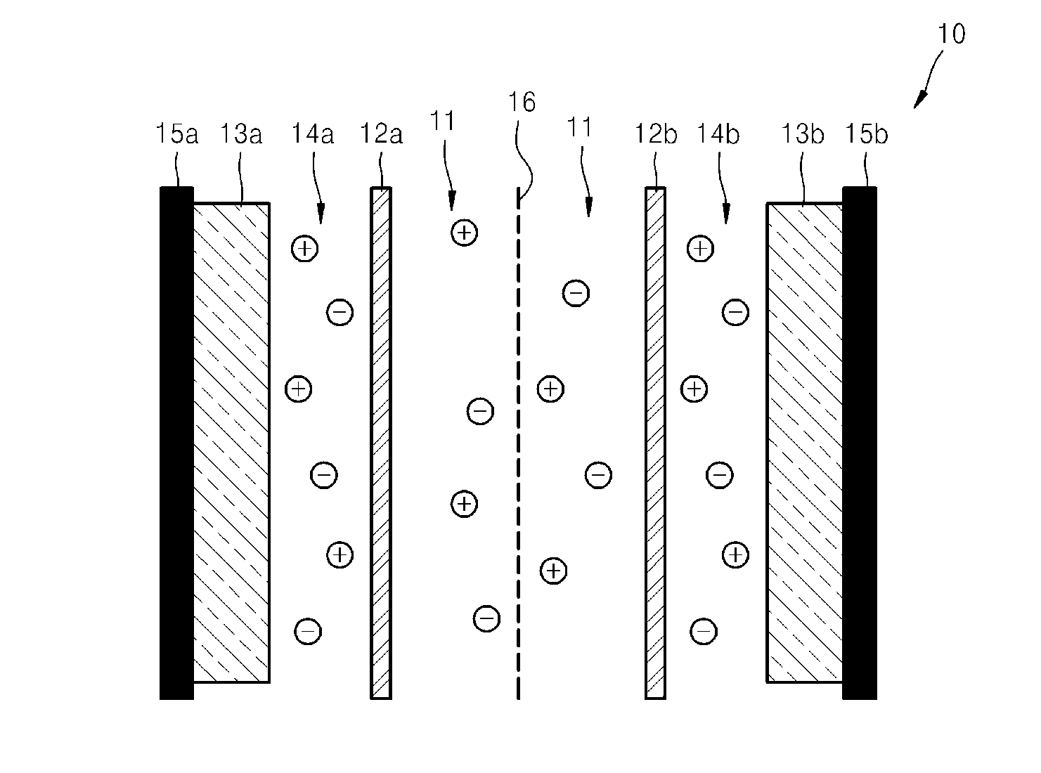
A capacitive deionization device includes; at least one flow path configured for influent water flow, at least one pair of electrodes, at least one charge barrier disposed between the at least one flow path and a corresponding electrode of the at least one pair of electrodes, and at least one electrolyte solution disposed between the at least one electrode of the at least one pair of electrodes and a corresponding charge barrier of the at least one charge barrier, wherein the at least one electrolyte solution is different in at least one of ionic concentration and ionic species from the influent water.

Description

CROSS-REFERENCE TO RELATED APPLICATIONS[0001]This application claims priority to Korean Patent Application No. 10-2009-0077161, filed on Aug. 20, 2009, and all the benefits accruing therefrom under 35 U.S.C. §119, the content of which in its entirey of which is incorporated herein by reference.BACKGROUND[0002]1. Field[0003]The present disclosure relates to a capacitive deionization device, and more particularly, a capacitive deionization device including an electrolyte solution having ionic species contained therein, the types and / or total concentration of which differ from those of ionic species contained in influent water to the capacitive deionization device.[0004]2. Description of the Related Art[0005]Tap water supplied to homes contains hardness components, e.g., various water-hardening minerals such as calcium, though the contents thereof vary according to the region where the home is located. In particular, in Europe where large amounts of limestone components flow into under...

Claims


Application Information

Patent Timeline
IPC IPC(8): C25B9/00H01R43/00
CPCC02F1/001Y10T29/49117C02F1/4691C02F1/461
Inventor KIM, CHANG-HYUNKANG, HYO-RANGYANG, HO-JUNGSONG, TAE-WONKIM, HYUN-SEOKHAN, SUNG-SOO
Owner SAMSUNG ELECTRONICS CO LTD
Learn More