Medicine feeder and medicine dispenser

Inactive Publication Date: 2011-02-24
YUYAMA MFG CO LTD
View PDF6 Cites 32 Cited by
  • Summary
  • Abstract
  • Description
  • Claims
  • Application Information

AI Technical Summary

Benefits of technology

[0015]As described, in cases where a tablet is jammed, the medicine feeder and the medicine dispenser according to the present invention are capable of attempting to clear the jammed tablet by driving the rotor in a reverse rotation directio

Problems solved by technology

In this dispensing process in the medicine dispenser, there are cases where a tablet is jammed to seize and disable the rotor from rotation due to a tro

Method used


Image

  • Medicine feeder and medicine dispenser
  • Medicine feeder and medicine dispenser
  • Medicine feeder and medicine dispenser

Examples


first embodiment

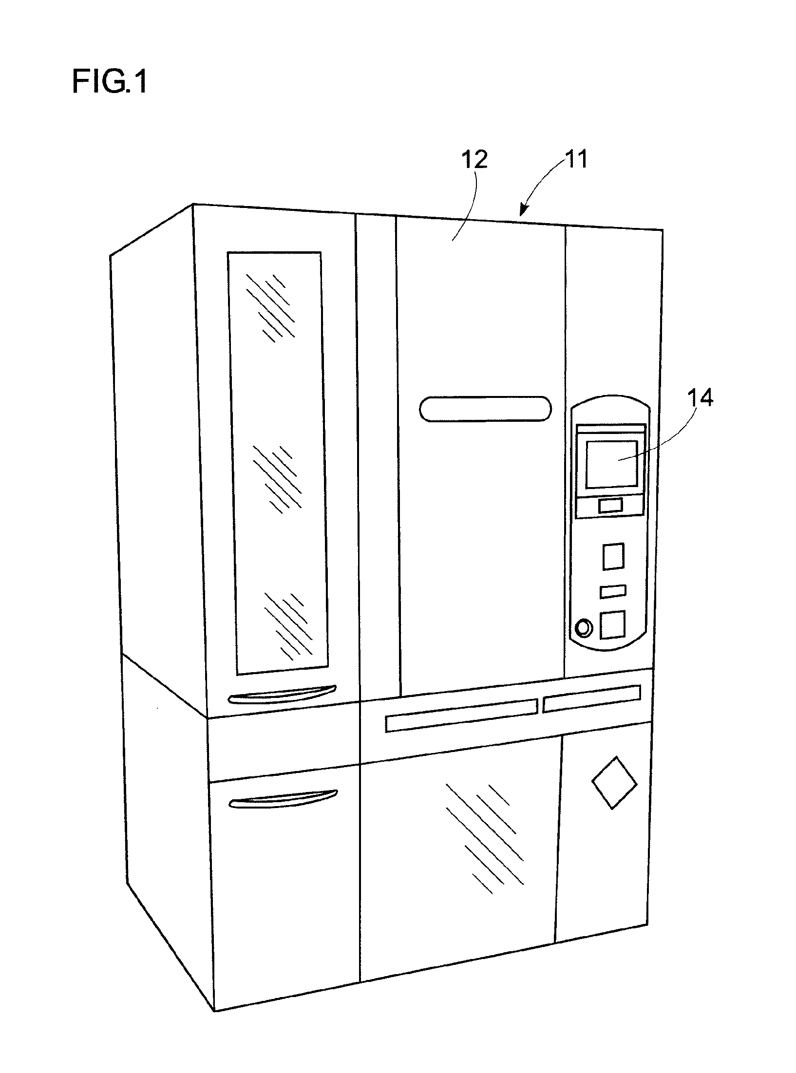
[0043]As shown in FIG. 1, a medicine dispenser 11 according to a first embodiment incorporates a large number of medicine feeders 13 (see FIG. 2) behind a front door 12. Also, an operation display panel 14 is provided on the right of the door 12.

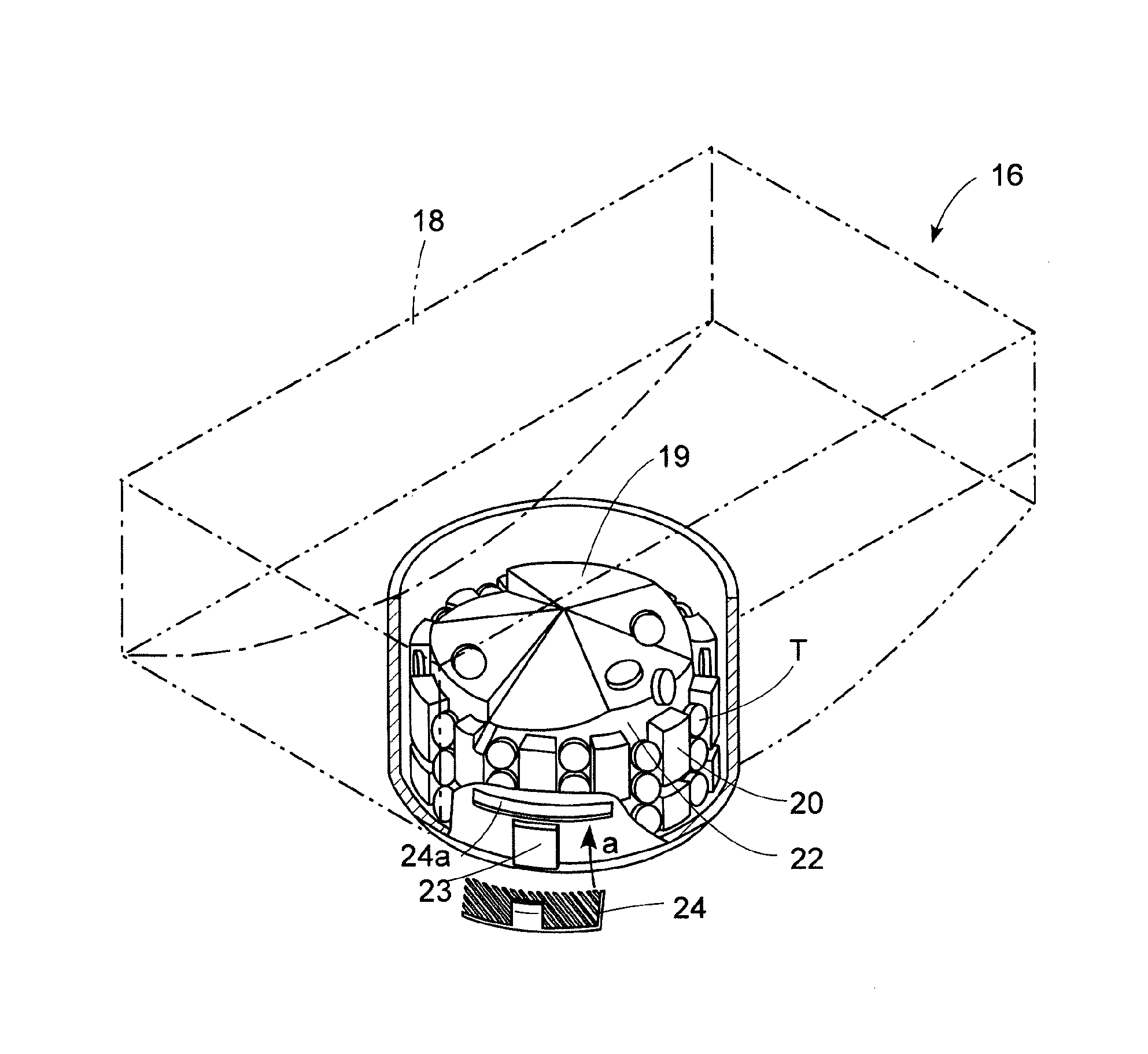
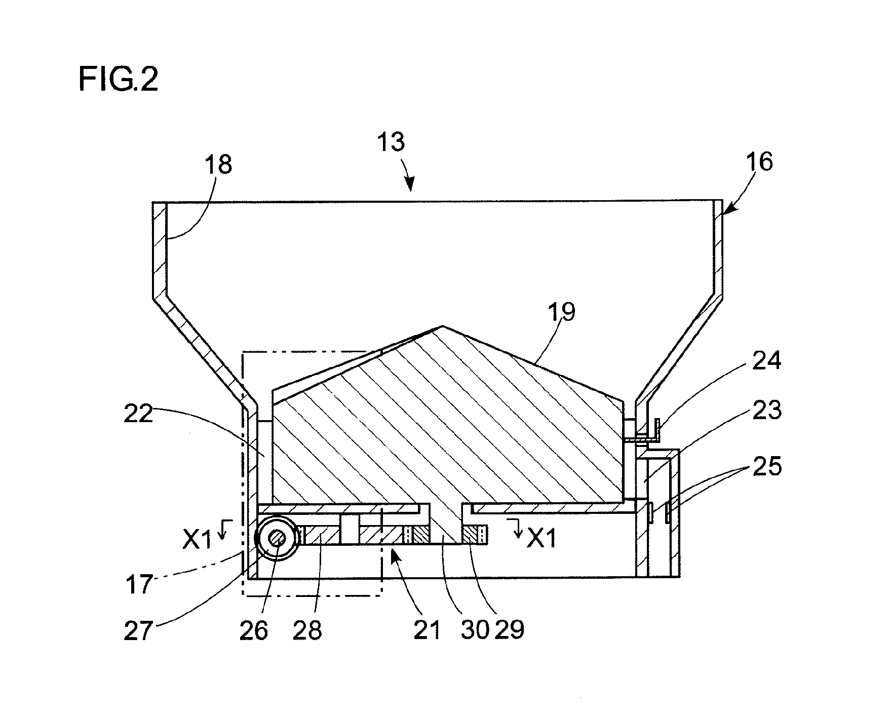
[0044]As shown in FIG. 2, the medicine feeder 13 is composed of a dispensing cassette 16 and a drive unit 17. The dispensing cassette 16 is conventional (see Patent Document 1), and includes a medicine storage 18 which stores tablets, a rotor 19 provided at a bottom of the medicine storage 18, a gear transmission section 21 provided at a bottom surface of the medicine storage 18, and other components.

[0045]Drive power from the drive unit 17 is transmitted via the gear transmission section 21 to rotate the rotor 19, and in this rotation, tablets T (see FIG. 3) in the medicine storage 18 are distributed into pockets 22 between a large number of vertical ribs 20 provided in an outer circumferential surface of the rotor 19. Near a dispensing spo...

second embodiment

[0099]A medicine dispenser 11 shown in FIG. 17 through FIG. 22 according to the second embodiment is essentially the same as the first embodiment (see FIG. 1) in its basic configuration. Also, a medicine feeder 13 includes a dispensing cassette 16 of the same configuration as in the previous embodiment (see FIG. 2 through see FIG. 4). However, there are some differences in an internal structure of a drive unit 17.

[0100]Specifically, as shown in FIG. 17 and FIG. 18, the drive unit 17 according to the second embodiment has a drive motor 38, and a switching solenoid 71 (hereinafter, simply called solenoid 71) as a switching actuator. A motor shaft 41 of a drive motor 38 is parallel with a plunger 72 of the solenoid 71. Further, these two members are perpendicular to an output shaft 31.

[0101]A worm gear 73 is mounted to the motor shaft 41, and the worm gear 73 engages with a worm ring 74, which is mounted rotatably to a case 75. The worm ring 74 is a two-stage gear, which has a small-di...

third embodiment

[0114]FIG. 23 shows a medicine feeder according to a third embodiment, which includes a drive unit 17 having a drive motor 38 and a switching motor 39. Their motor shafts 41, 42 are perpendicular to each other, and a slide shaft 83 is provided in parallel to the motor shaft 41. The slide shaft 83 is rotatable integrally with an output shaft 31 via a damper 84. A coupling 32 is attached to a tip of the output shaft 31.

[0115]Between the motor shaft 41 of the drive motor 38 and the output shaft 31, a normal-rotation transmission path 45 and a reverse-rotation transmission path 46 are provided. The normal-rotation transmission path 45 is constituted by a drive gear 85 attached to the motor shaft 41, and an output gear 86 engaged therewith. The output gear 86 is coaxial with the slide shaft 83. The output gear 86 has a boss with an internal recess formed with a female spline 88 (see FIG. 24A) for engagement by a male spline 89 provided on the slide shaft 83.

[0116]The reverse-rotation tra...


PUM


Abstract

An object of the present invention is to clear a jammed tablet in a medicine feeder upon detection thereof, through improvements on a drive unit so that reverse rotation of a rotor can be achieved without driving a motor in reverse rotating direction, i.e., while the motor is in normal rotation setting. A medicine feeder's drive unit includes a drive motor, a gear transmission device, an output shaft and a switcher. The gear transmission device is constituted by a normal-rotation transmission path and a reverse-rotation transmission path provided between a motor shaft of the drive motor and the output shaft. The switcher selects one of the transmission paths for output of driving power from the drive motor.

Description

TECHNICAL FIELD[0001]The present invention relates to a medicine feeder for storing tablets, capsules or other solid-type medicines by the kind and dispensing these medicines one by one in predetermined numbers based on prescribing information. The invention also relates to a medicine dispenser including a plurality of the medicine feeders.BACKGROUND ART[0002]A dispenser of solid medicines (hereinafter simply called “tablet(s)”, includes a predetermined number of cassette-type medicine feeders for dispensing tablets one by one. In the medicine feeder, a medicine storage has a bottom provided with a rotor. The rotor has an outer circumferential surface formed with a large number of pockets, and as the rotor rotates, tablets in the medicine storage are dispensed one by one from a dispensing spout (Patent Document 1).[0003]In this dispensing process in the medicine dispenser, there are cases where a tablet is jammed to seize and disable the rotor from rotation due to a trouble caused b...

Claims


Application Information

Patent Timeline
IPC IPC(8): B65D83/04B65H3/00
CPCG07F9/026G07F17/0092G07F11/44G07F11/005B65B1/10B65B1/30B65B37/08B65B57/00B65B57/18B65B57/20B65B65/02
Inventor KOIKE, NAOKIMAEDA, AKIRA
Owner YUYAMA MFG CO LTD
Why Eureka
Try Eureka