

Surface Acoustic Wave Device and Communication Apparatus Using Same
a surface acoustic wave and communication apparatus technology, applied in piezoelectric/electrostrictive/magnetostrictive devices, piezoelectric/electrostriction/magnetostriction machines, electrical apparatus, etc., can solve the problems of inability to secure sufficient power durability performance, and difficulty in sufficiently secure electric characteristics of communication apparatus operating at a high frequency, and achieve high-reliability communication apparatus and sufficient power durability performance
- Summary
- Abstract
- Description
- Claims
- Application Information
AI Technical Summary
Benefits of technology
Problems solved by technology
Method used
Image

Examples
embodiments of invention
[0037]Below, examples of embodiments of a SAW device of the present invention be explained in detail based on the drawings. Note that, the drawings used in the following embodiments are schematic ones. Accordingly, the dimensions, ratios, etc. on the drawings do not necessarily coincide with the real ones.
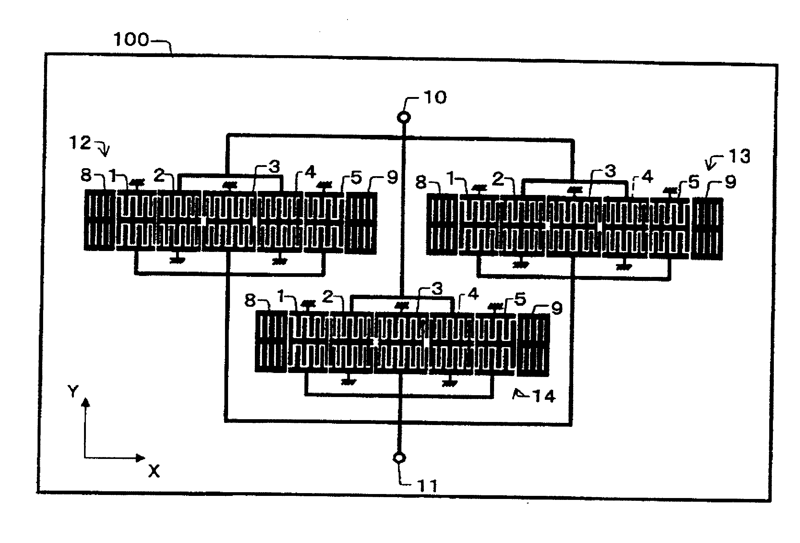
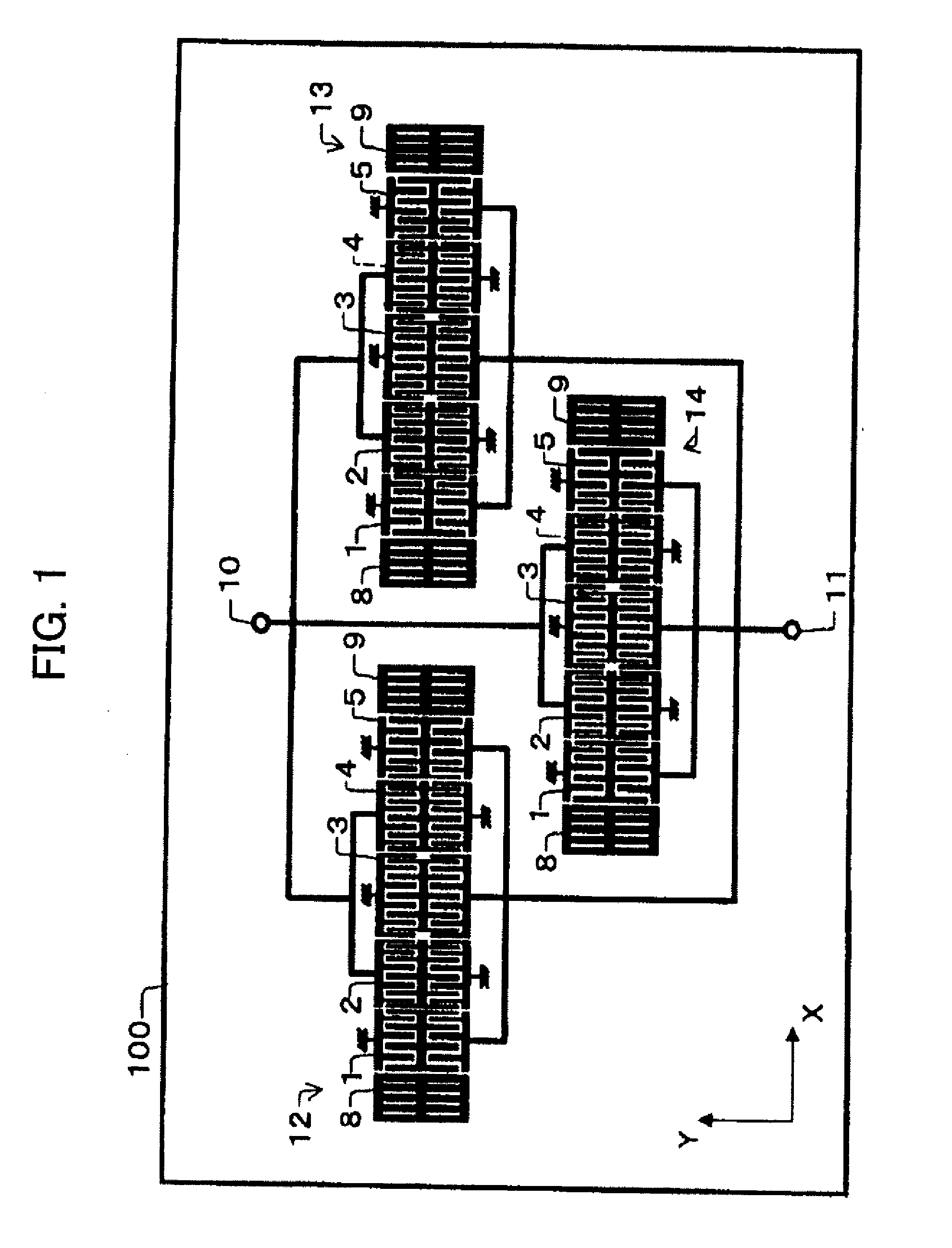
[0038]FIG. 1 is a plan view showing a SAW device according to an embodiment of the present invention. Note that, in the following drawings, the same portions are assigned the same notations.
[0039]As shown in FIG. 1, the SAW device of the present embodiment is mainly configured of a piezoelectric substrate 100 and three SAW elements 12, 13, and 14 formed on the piezoelectric substrate 100.
[0040]The piezoelectric substrate 100 is made of for example an LiNbO3 substrate, LiTaO3 substrate, or the like. Note that, on the main surface of the piezoelectric substrate 100, along an outer circumferential edge, annular electrodes for tightly sealing the SAW elements 12, 13, and 14, signal ele...
first modification example
[0059]FIG. 3 is a plan view showing a first modification example of the SAW device shown in FIG. 1.
[0060]The SAW device shown in FIG. 3 has six SAW elements 12 to 17 each of which has three serially divided IDT electrodes 1 to 3 provided with a plurality of electrode fingers which are long in a direction perpendicular to the propagation direction of the SAW propagating on the piezoelectric substrate 100 and arranged along the propagation direction and has reflector electrodes 8 and 9 arranged at the two sides of three IDT electrodes 1 to 3 and provided with a plurality of electrode fingers which are long in the direction perpendicular to the propagation direction. The six SAW elements 12 to 17 are connected in parallel. Each of the six SAW elements 12 to 17 has comb-shaped electrode structure that IDT electrodes 1 to 3 mesh at the two sides of the center bus bar 20o.
[0061]Each IDT electrode according to this modification example has the same electrode finger structure as that of th...
second modification example
[0062]FIG. 4 is a plan view showing a second modification example of the SAW device shown in FIG. 1.
[0063]The SAW device shown in FIG. 4 has two SAW elements 12 and 13 each of which has seven serially divided IDT electrodes 1 to 7 provided with a plurality of electrode fingers which are long in the direction perpendicular to the propagation direction of the SAW propagating on the piezoelectric substrate 100 and arranged along the propagation direction and has reflector electrodes 8 and 9 arranged at the two sides of seven IDT electrodes 1 to 7 and provided with a plurality of electrode fingers which are long in the direction perpendicular to the propagation direction. The two SAW elements 12 and 13 are connected in parallel. Each of the two SAW elements 12 and 13 has comb-shaped electrode structure that IDT electrodes 1 to 7 mesh at the two sides of the center bus bar 20o.
[0064]Each IDT electrode according to this modification example has the same electrode finger structure as the ...
PUM
 Abstract
Description
Claims
Application Information