Image stabilization control circuit

a control circuit and image stabilization technology, applied in the field of can solve the problems of difficult configuration of corrective circuits within the image stabilization control circuits with fixed logic circuitry, and achieve the effect of reducing the effect of image capture displacemen

Active Publication Date: 2011-02-24
SEMICON COMPONENTS IND LLC
View PDF21 Cites 25 Cited by
  • Summary
  • Abstract
  • Description
  • Claims
  • Application Information

AI Technical Summary

Benefits of technology

[0018]The image stabilization control circuit according to the present invention is used for an image pickup apparatus comprising a vibration-detecting element, a vibration-compensating mechanism having a moveable component, and a position-detecting element for detecting a driving position of the moveable component, the displacement of the moveable component reducing the effect of image-capture displacement resulting from vibration of the image pickup apparatus; wherein the image stabilization control circuit comprises: a current position signal-generating part for generating a current position signal for indicating a current position of the moveable part, based on a signal outputted by the position-detecting element; a shake displacement signal-generating part for generating a shake displacement signal in accordance with the degree of shake displacement of the image pickup apparatus, based on a signal outputted by the vibration-detecting element; a target position signal-generating part for correcting the shake displacement signal based on a pre-set correction function and generating a target position signal for indicating a target position for the moveable component; and a displacement control signal-generating part for generating a displacement control signal for instructing the vibration-compensating mechanism to displace the moveable component from the current position to the target position, based on the target position signal and the current position signal; the target position signal-generating part comprises: a memory part for storing, as the correction function, a corresponding relationship between the shake displacement signal and the target position signal configured based on a relationship between the driving position of the moveable component and the current position signal; and a processor for calculating the target position signal from the shake displacement signal, based on the correction function.

Problems solved by technology

However, any error related to the characteristics or installation position of the position-detecting element itself may prevent the magnitude of the signal from being proportional to the degree of displacement from a reference position, as shown in FIG. 5.
A problem is presented when a moveable component is driven towards a target position generated based on a signal outputted by a vibration-detecting element, inasmuch as the displacement of the moveable component will not be of the inherently required value if, e.g., the driving control signal is generated based on the assumption that the position-detecting element has a linear characteristic.
However, the characteristics of each of the position-detecting elements are inconsistent from one element to another, and it is therefore difficult to configure a corrective circuit within the image stabilization control circuit with fixed logic circuitry.

Method used


Image

  • Image stabilization control circuit
  • Image stabilization control circuit
  • Image stabilization control circuit

Examples


Embodiment Construction

[0024]An embodiment of the present invention (“the embodiment” hereafter) will now be described with reference to the accompanying drawings.

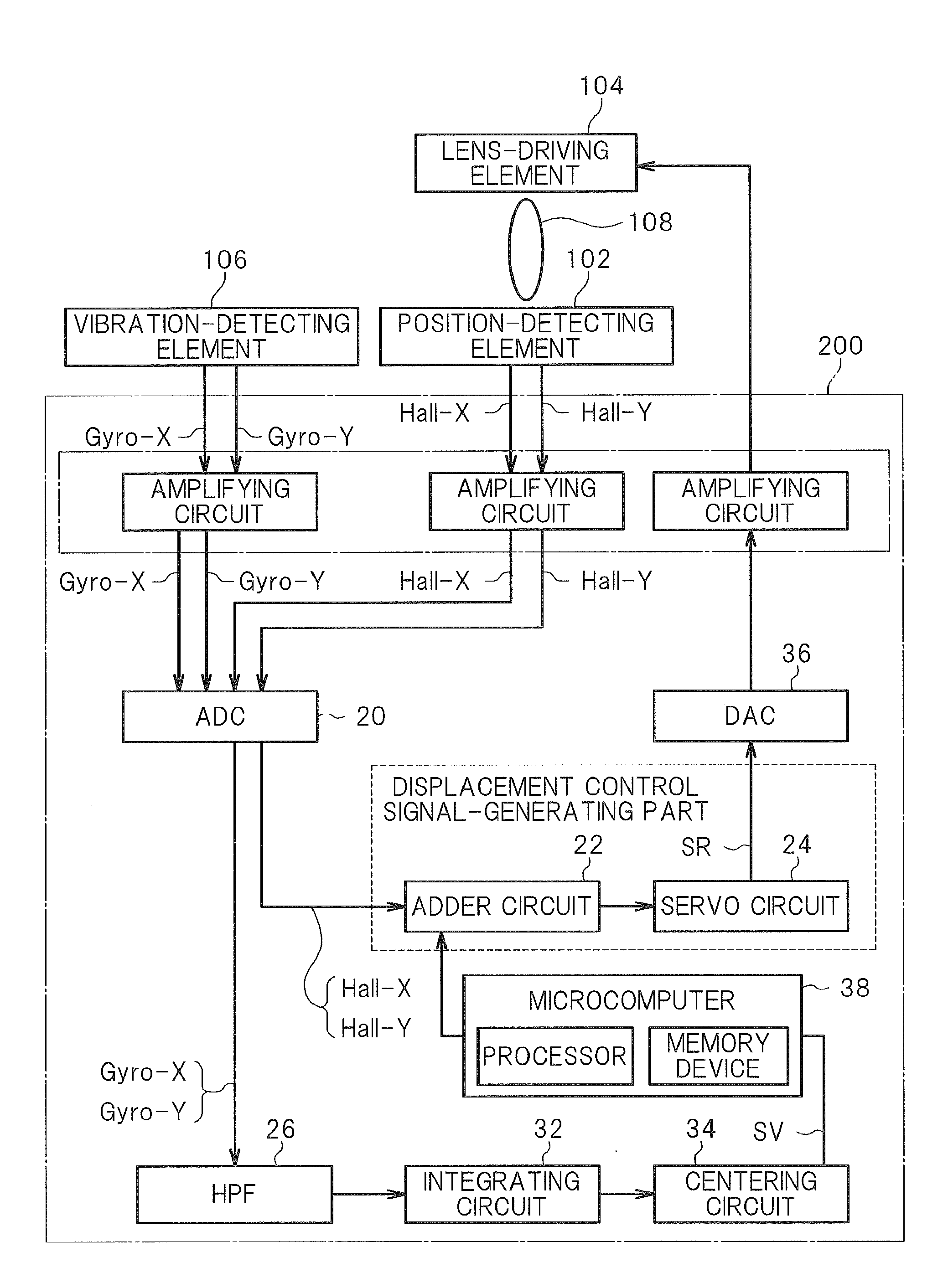
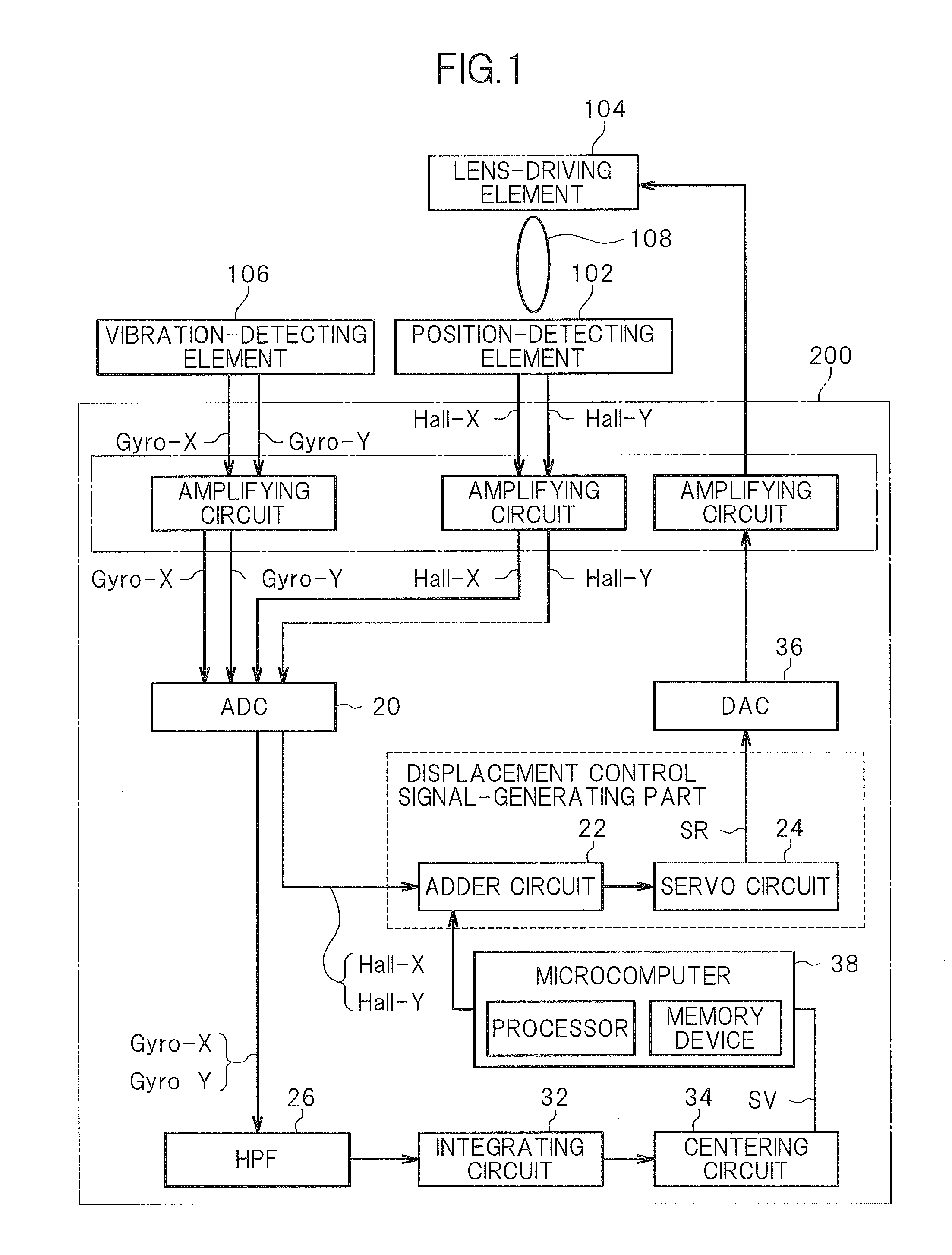
[0025]An image stabilization control circuit 200 that is an embodiment of the present invention comprises an ADC 20, an adder circuit 22, a servo circuit 24, a high-pass filter (HPF) 26, an integrating circuit 32, a centering circuit 34, a DAC 36, and a microcomputer 38, as shown in a function block diagram shown in FIG. 1.

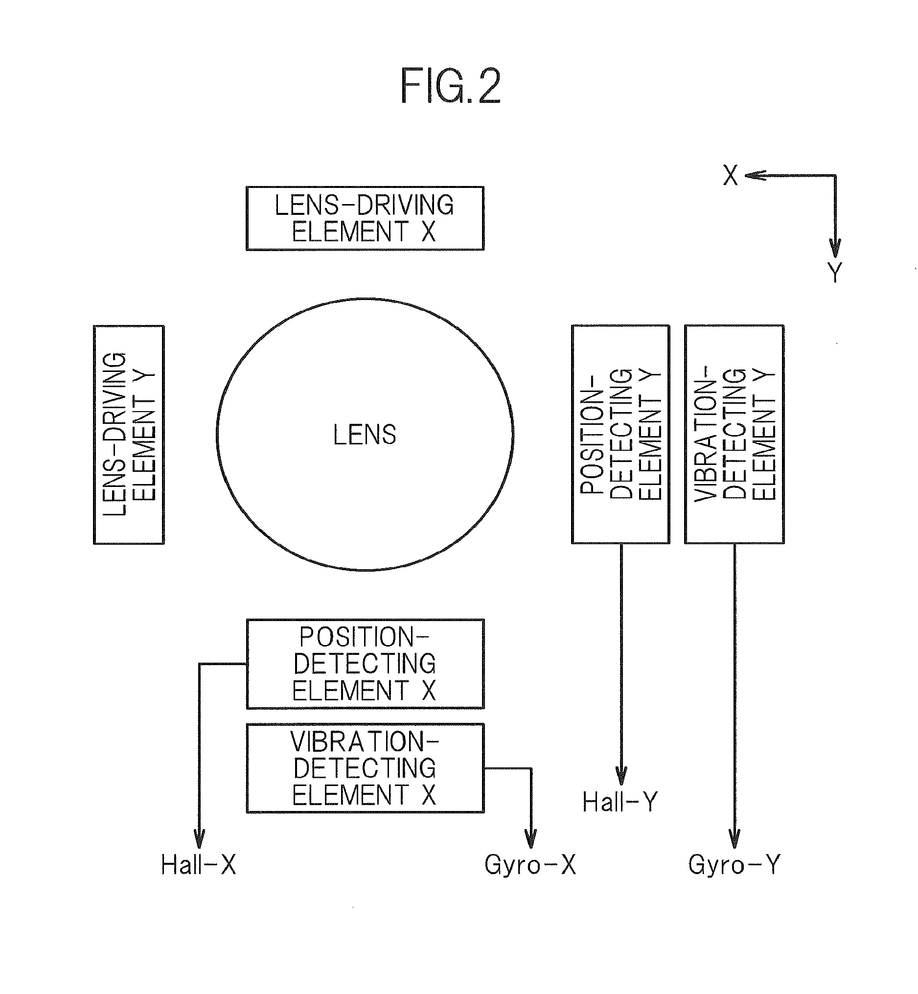
[0026]The image stabilization control circuit 200 is connected to a position-detecting element 102, a lens-driving element 104, and a vibration-detecting element 106. The elements are similar to those described in the prior art. Specifically, the position-detecting element 102 is provided in relation to two or more axes in order to measure the position, within at least an x-y plane, of the lens 108 driven by the lens-driving element 104. The vibration-detecting element 106 is also provided in relation to two or more axes in or...


PUM


Abstract

The accuracy of servo control of a corrective lens in an image stabilization control circuit is prevented from decreasing due to non-linear characteristics of a position-detecting element. A signal representing a component of vibration of an image pickup apparatus is generated based on an angular velocity signal from a vibration-detecting element. A microcomputer corrects the vibration component signal according to a predetermined correction function and generates a target position signal representing a target position of the lens. A position-detection signal based on an output from the position-detecting element is compared with the target position signal, and the position of the lens is servo-controlled. The correction function is set so that the characteristics of variation of the target position signal relative to the target position will be the same as the characteristics of variation of the position-detection signal relative to the actual position of the lens.

Description

CROSS-REFERENCE TO RELATED APPLICATION[0001]The present application claims priority from Japanese application JP 2009-002284 filed on Jan. 8, 2009, the content of which is hereby incorporated by reference into this application.BACKGROUND OF THE INVENTION[0002]1. Field of the Invention[0003]The present invention relates to an image stabilization control circuit used for an image pickup apparatus.[0004]2. Description of the Related Art[0005]In recent years, the quality of images handled by image pickup apparatuses such as digital still cameras and digital video cameras has been enhanced by increasing the number of pixels handled by an imaging element installed in the device. Another desired method for enhancing the quality of images captured by image pickup apparatuses involves providing the image pickup apparatuses with a hand-shake correction function in order to prevent blurring of a target image due to vibration generated when the hand(s) holding the image pickup apparatus shake o...

Claims


Application Information

Patent Timeline
Patent Type & Authority Applications(United States)
IPC IPC(8): H04N5/228
CPCG02B27/646G03B5/00G03B2205/0007G03B2217/005H04N5/23258H04N5/23287G03B2205/0069H04N5/23248H04N23/68H04N23/6812H04N23/687
Inventor WATANABE, TOMOFUMIYAMAGATA, DAVID FUMIAKI
Owner SEMICON COMPONENTS IND LLC
Why Eureka
Try Eureka