Protection apparatus of load circuit

a load circuit and protection apparatus technology, applied in the direction of emergency protective arrangements for limiting excess voltage/current, emergency protective arrangements responsive to undesired changes, electrical apparatus, etc., can solve the problems of deterioration of fuses fb>1/b> and fb>2/b>, and become difficult to miniaturize electric wires and semiconductor switches. , to achieve the effect of reducing the weight of electric wires and semiconductor switches, and improving fuel consumption

Active Publication Date: 2011-02-24
YAZAKI CORP
View PDF6 Cites 36 Cited by
  • Summary
  • Abstract
  • Description
  • Claims
  • Application Information

AI Technical Summary

Benefits of technology

[0022]In the protection apparatus of a load circuit according to the present invention, the circuit is broken before the temperature of the electric wire reaches the actual allowed temperature thereof, and the electric wire, the semiconductor switch, the load and the like are protected from overheating. Moreover, unlike the conventional fuses, no deterioration occurs owing to the rush currents and the repetition of the ON / OFF of the loads, and it is not necessary to ensure the margin for the breaking temperature. Therefore, it becomes possible to achieve the miniaturization / weight reduction of the electric wire and the semiconductor switch. Hence, an effect of improving fuel consumption can be exerted.

Problems solved by technology

Therefore, in some case, erroneous breakdown of the fuses F1 and F2 occurs, which results from the deterioration of the fuses F1 and F2.
As a result, it is necessary to use electric wires, semiconductor switches and the like, which are adapted to characteristics of the fuses for which the margin is considered, and it has become difficult to miniaturize the electric wires and the semiconductor switches, which are used for the load circuit.

Method used


Image

  • Protection apparatus of load circuit
  • Protection apparatus of load circuit
  • Protection apparatus of load circuit

Examples


first embodiment

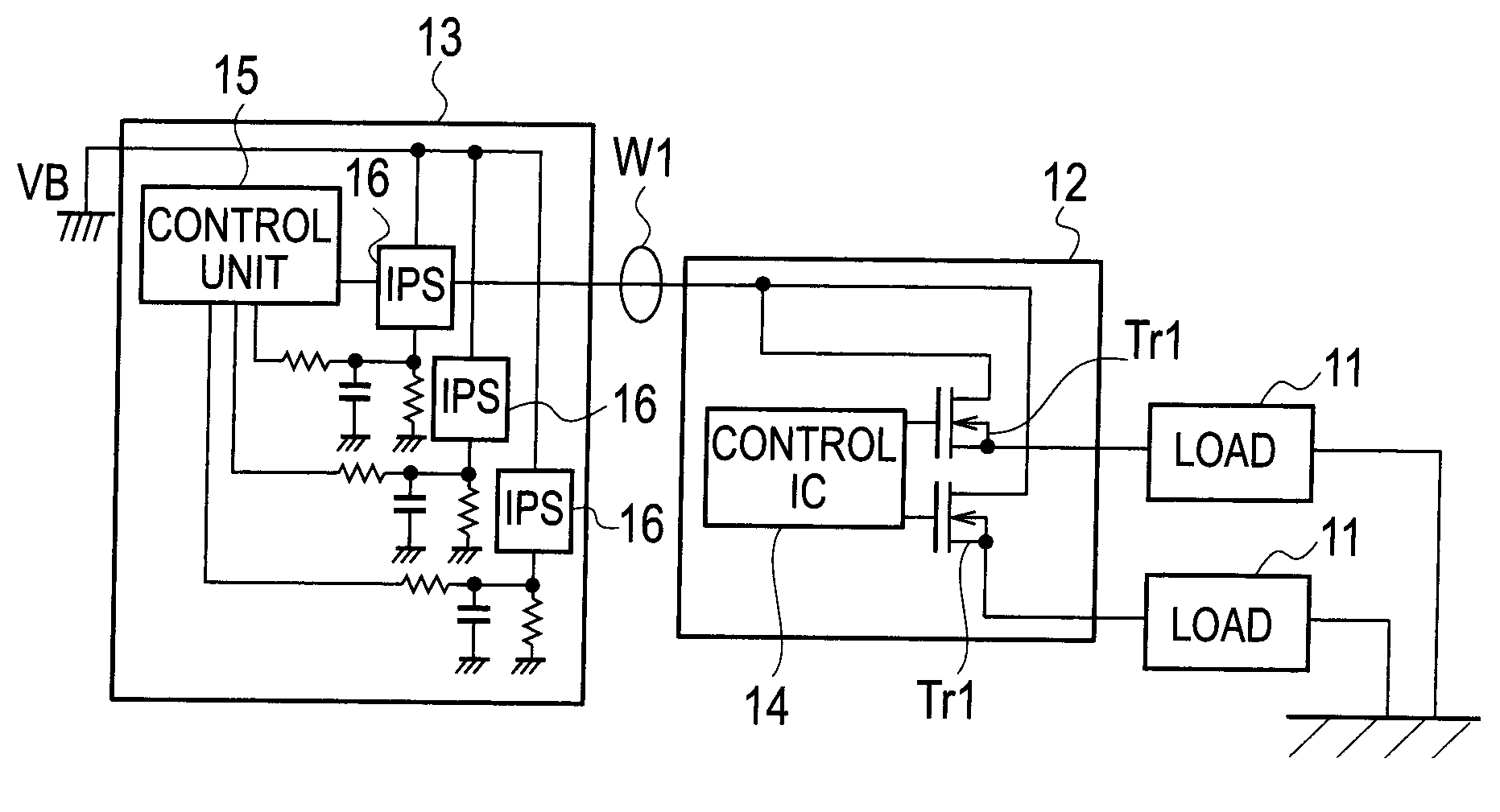
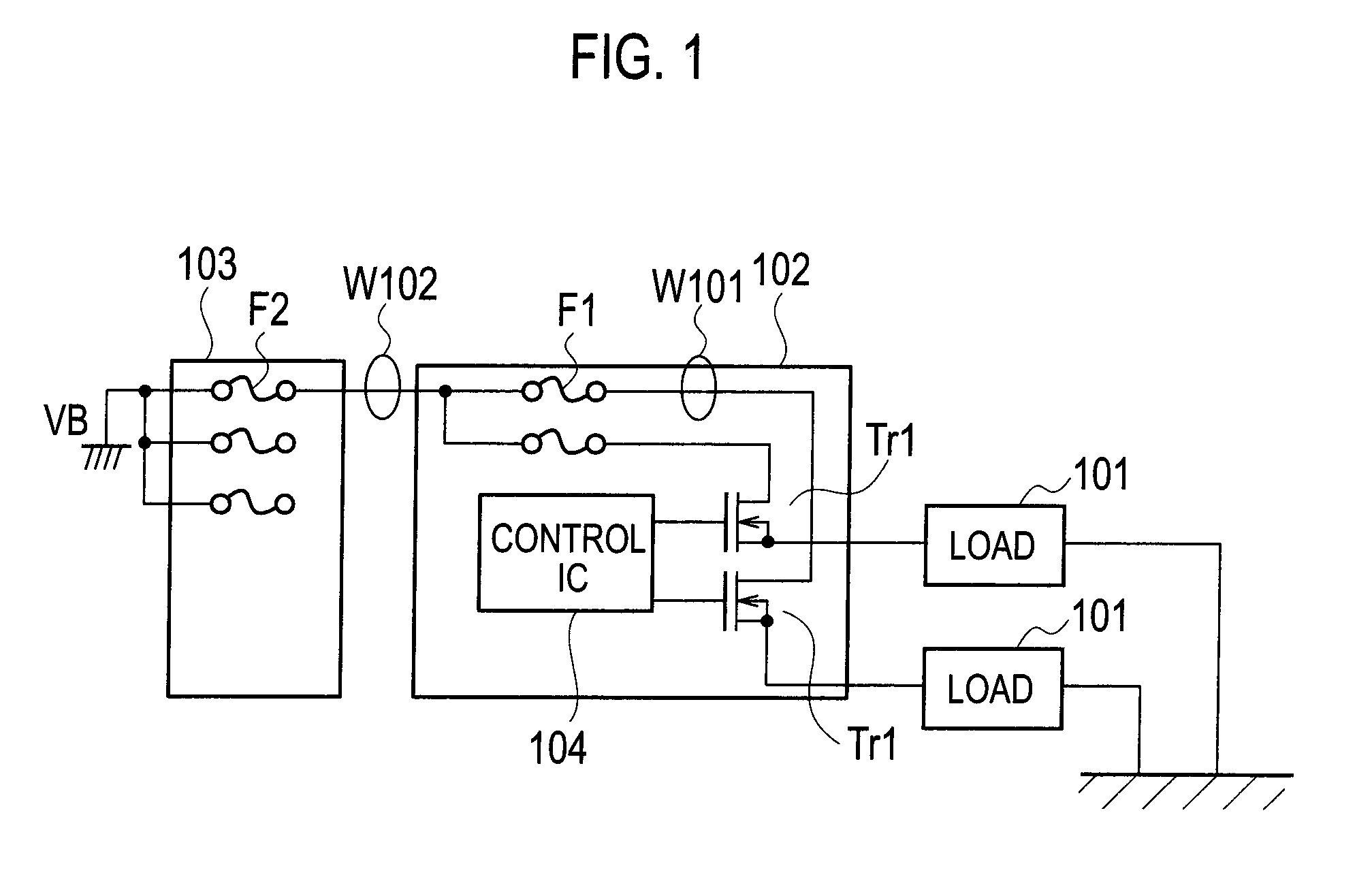
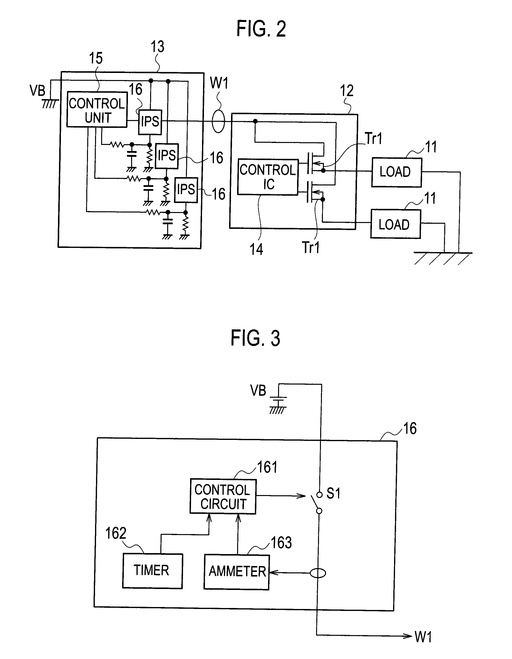
[0059]FIG. 3 is a block diagram showing a detailed configuration of each of the switch circuits 16 according to a first embodiment of the present invention. As shown in FIG. 2, each of the switch circuits 16 includes: a semiconductor relay S1 (switch portion); an ammeter 163 that detects a current flowing through the electric wire W1; a timer 162 that counts an elapsed time while the current is flowing through the electric wire W1; and a control circuit 161 that controls ON / OFF of the semiconductor relay S1 based on a value of the current detected by the ammeter 163 and on the time counted by the timer 162.

[0060]The control circuit (temperature estimation unit, breaking control unit) 161 estimates a virtual temperature of the electric wire W1 (not an actual temperature of the electric wire W1 but a temperature defined by a pseudo-temperature arithmetic expression) based on a method to be described later (estimation method of the electric wire temperature by the pseudo-temperature ar...

second embodiment

[0120]A description is made below of a second embodiment of the present invention based on the drawings.

[0121]FIG. 19 is a block diagram showing a detailed configuration of each of switch circuits 16 according to the second embodiment of the present invention. As shown in FIG. 19, each of the switch circuits 16 includes: the semiconductor relay (switch portion) S1; the ammeter 163 that detects the current flowing through the electric wire W1; the timer 162 that counts the elapsed time while the current is flowing through the electric wire W1; and a control circuit 161a that controls ON / OFF of the semiconductor relay S1 based on the current detected by the ammeter 163 and on the time counted by the timer 162. The control circuit 161a includes functions as a first temperature arithmetic operation unit, a second temperature arithmetic operation unit and an overcurrent determination unit, which is described later.

[0122]The control circuit 161a estimates the virtual temperature of the el...


PUM


Abstract

A protection apparatus of a load circuit, comprises: a temperature estimation unit configured to estimate a temperature of an electric wire based on a pseudo-temperature arithmetic expression; and a breaking control unit configured to break a switch portion when the temperature estimated by the temperature estimation unit has reached an allowed temperature of the electric wire. The pseudo-temperature arithmetic expression is set in such a manner that, in a temperature arithmetic expression of the electric wire, the temperature arithmetic expression using the elapsed time counted by the timer, the current detected by the current detection unit, and a heat capacity and conductor resistance of the electric wire, a pseudo-heat capacity smaller than the heat capacity of the electric wire is assigned to the heat capacity, and a pseudo-conductor resistance larger than the conductor resistance of the electric wire is assigned to the conductor resistance.

Description

TECHNICAL FIELD[0001]The present invention relates to a protection apparatus of a load circuit, which protects the load circuit by breaking the load circuit instantaneously when an overcurrent flows through the circuit to raise temperature of an electric wire and a semiconductor switch.BACKGROUND ART[0002]A load circuit mounted on a vehicle supplies electric power to loads such as a bulb and a motor. This load circuit includes a battery and semiconductor switches (MOSFETs or the like) provided between the battery concerned and the loads. The battery, the semiconductor switches and the loads are connected to one another through conductors including electric wires. In the load circuit, a control circuit that outputs drive / stop signals for switching ON / OFF the semiconductor switches is further provided. By the drive / stop signals, the loads are switched between driving and stopping.[0003]In the above-described load circuit, fuses are provided. The fuses break the circuit instantaneously...

Claims


Application Information

Patent Timeline
Patent Type & Authority Applications(United States)
IPC IPC(8): H02H5/04
CPCH02H6/00H02H7/30H02H7/228
Inventor NAKAMURA, YOSHIHIDEMARUYAMA, AKINORIUETA, KEISUKE
Owner YAZAKI CORP
Why Eureka
Try Eureka