
Multicast distribution system and multicast distribution method

a multicast distribution and distribution method technology, applied in the field of multicast distribution system, can solve the problem of large load applied to the distribution source router, and achieve the effect of ensuring the scalability of multicast distribution and reducing bandwidth load

Active Publication Date: 2011-02-24
YAMAHA CORP
View PDF22 Cites 37 Cited by
  • Summary
  • Abstract
  • Description
  • Claims
  • Application Information

AI Technical Summary

Benefits of technology

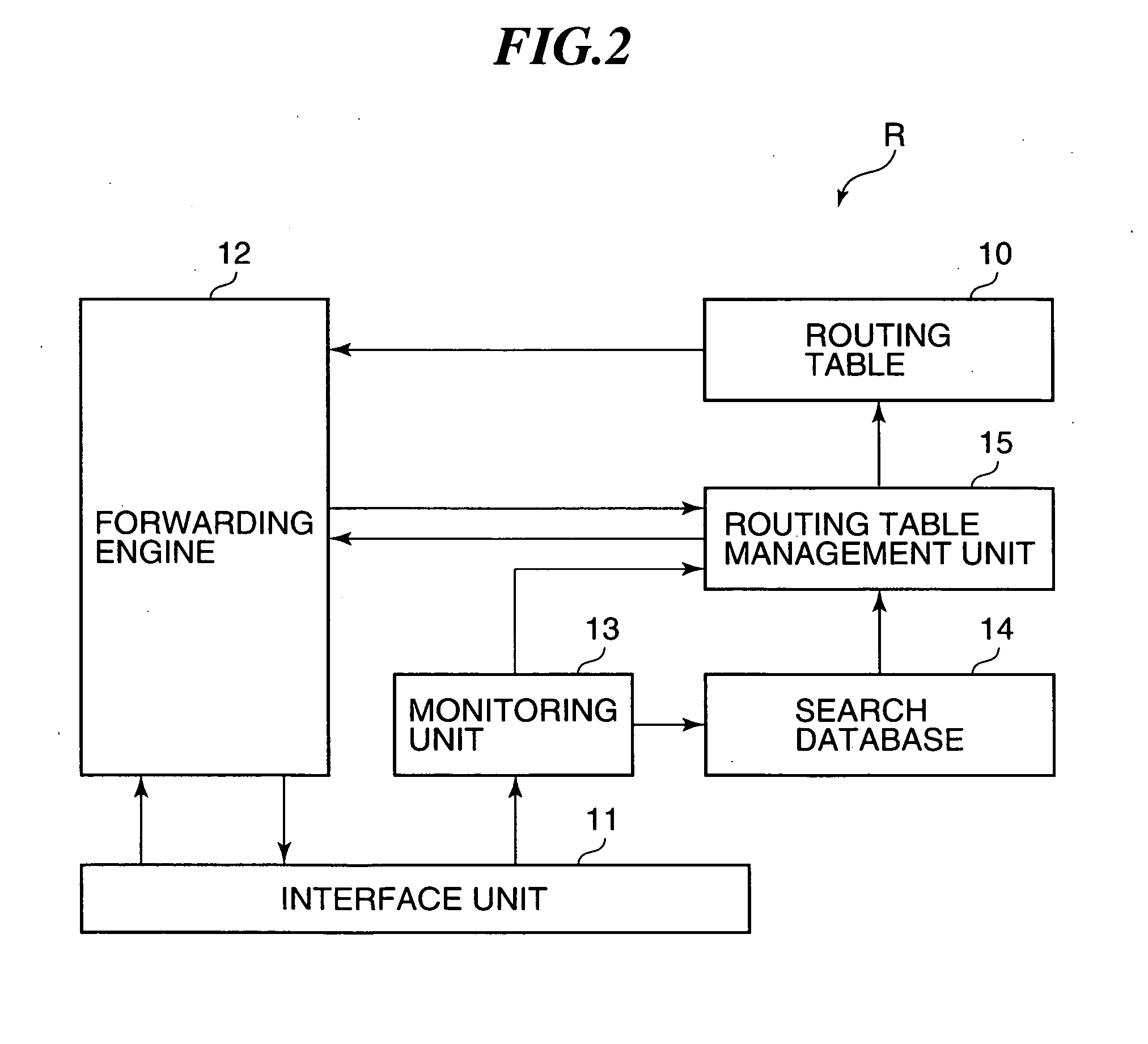
[0007]With this construction, the distribution source router performs multicast distribution to distribution destination routers of a multicast group constructed on a multicast network. The multicast network is formed on a mesh virtual network. The distribution source router monitors a CPU load ratio in the distribution source router, a communication characteristic of the multicast group, and a path characteristic of the mesh virtual network. The communication characteristic of the multicast group includes at least one of a bandwidth and a communication delay thereof, and is calculated by monitoring packets for the multicast group. The path characteristic of the mesh virtual network includes at least one of a bandwidth and a communication characteristic thereof, and is calculated by monitoring packets flowing on the mesh virtual network. Further, the distribution source router stores the CPU load ratio and the communication characteristic of the multicast group. In addition, the distribution source router starts reconstruction of a multicast tree based on the path characteristic of the mesh virtual network and at least one of a result of comparison between the CPU load ratio and a threshold value thereof and a result of comparison between the communication characteristic of the multicast group and a threshold value thereof. The distribution source router recreates a routing table based on the reconstructed multicast tree. As a result, a multicast distribution path can be selected according to a load status of the distribution source router, the communication characteristic of the multicast group, and the path characteristic of the mesh virtual network. Therefore, multicast distribution can be carried out by selecting a communication path that satisfies a communication characteristic requested by the multicast group. Even if a large load is applied to the distribution source router due to, e.g., the increase in number of distribution of packets, the CPU load ratio in the distribution source router can be maintained at or below a certain value (threshold value). Further, even if a communication delay or the like is caused in a part of virtual path on the mesh virtual network due to, e.g., the increase in number of packets flowing on the mesh virtual network, multicast distribution is performed by selecting a path having a path characteristic margin, whereby multicast distribution can be performed without causing a communication delay or the like. In this manner, since load of the distribution source router and bandwidth load of an actual path constituting the mesh virtual network can be reduced, it is possible to ensure the scalability of multicast distribution without the need of investment of hardware facilities for the distribution source router and the actual network.
[0009]With this construction, the distribution source router changes the number of branches and the depth of the multicast tree in a case where at least one of the CPU load ratio and the communication characteristic of the multicast group exceeds the threshold value thereof. Based on the number of branches and the depth of the multicast tree after change and the path characteristic of the mesh virtual network, the distribution source router starts reconstruction of the multicast tree. With the reconstructed multicast tree, multicast packets can be distributed via the distribution destination routers, without the need of directly distributing the multicast packets from the distribution source router to all the distribution destination routers, whereby the load of the distribution source router can reliably be deconcentrated.
[0011]With this construction, each of the distribution destination routers implements the reconstruction of the multicast tree that specifies the packet distribution path from the distribution source router based on the number of branches and the depth of the multicast tree and the path characteristic of the mesh virtual network. The distribution destination router monitors the path characteristic of the mesh virtual network and decides the packet distribution path based on the path characteristic of the mesh virtual network. The distribution destination router implements the recreation of the routing table based on the reconstructed multicast tree. The multicast tree is completed when the recreation of the routing tables for all the distribution destination routers are finished. Thus, the packet distribution path from the distribution destination router can be decided so as to select a communication path having a margin in consideration of the path characteristic of the mesh virtual network of the distribution destination routers. As a result, the distribution destination router is able to reduce a bandwidth load of an actual network that distributes multicast packets from the distribution destination router and constitutes the mesh virtual network, and it is therefore possible to ensure the scalability of multicast distribution without the need of investment of hardware facility of actual network.

Problems solved by technology

However, if the multicast routing protocol, e.g., PIM-SM, PIM-DM, or DVMRP, is used in a mesh virtual network, packets are transmitted from the distribution source router to all the routers, and therefore a large load is applied to the distribution source router.

Method used


Image

  • Multicast distribution system and multicast distribution method
  • Multicast distribution system and multicast distribution method
  • Multicast distribution system and multicast distribution method

Examples


Embodiment Construction

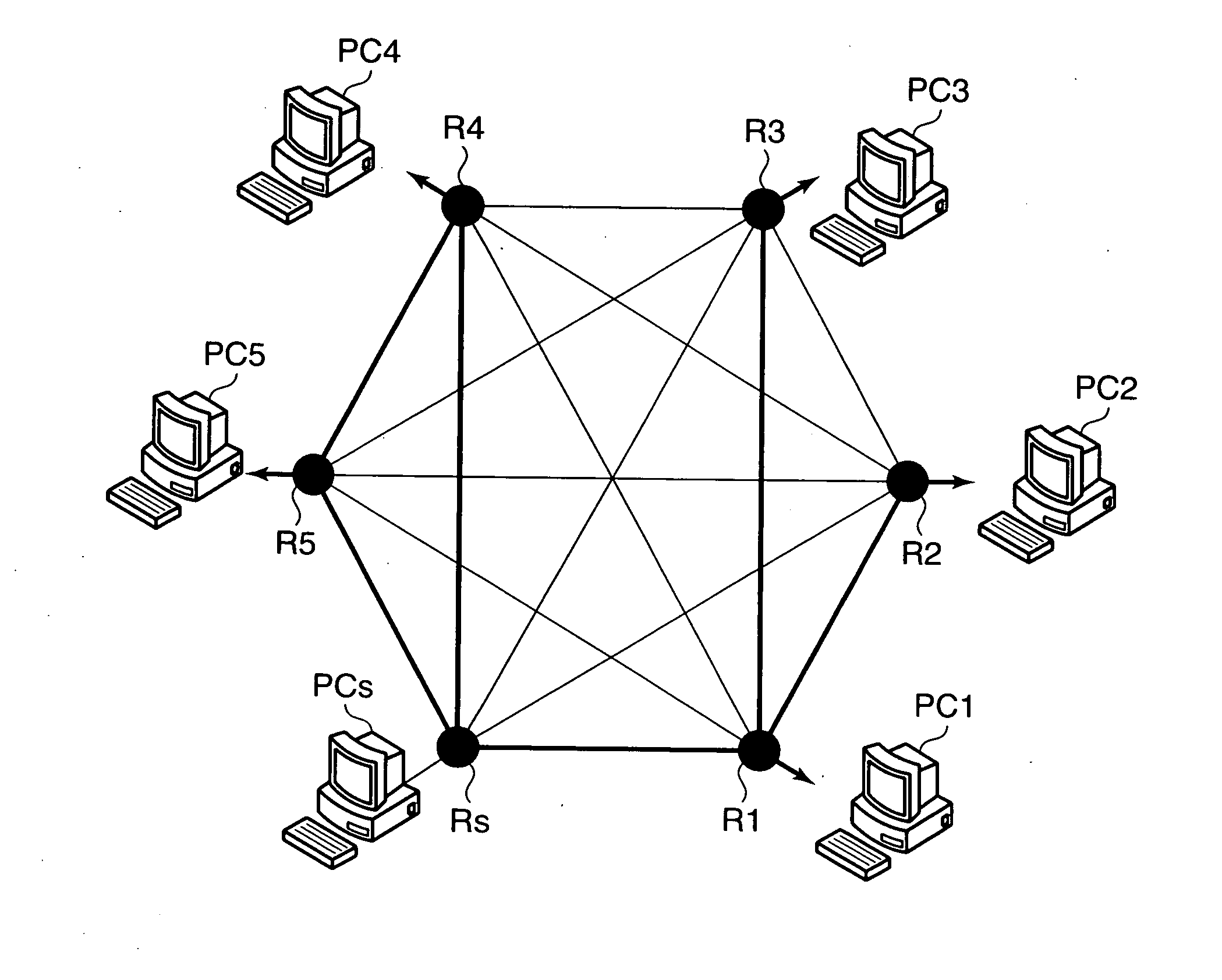
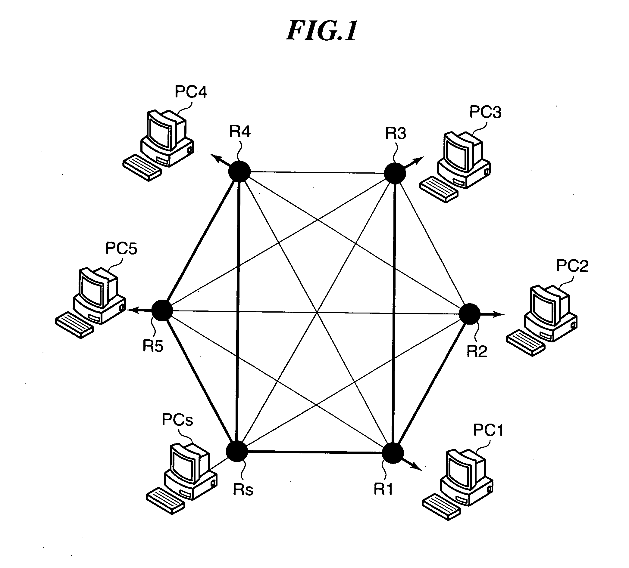
[0031]FIG. 1 illustrates multicast distribution performed between a plurality of routers connected to a mesh virtual network. As shown in FIG. 1, routers R (Rs and R1 to R5) are connected to the mesh virtual network and connected to respective ones of communication devices PC (PCs and PC1 to PC5) each implemented by e.g., a personal computer or a cell phone. In the illustrated example, the router Rs is a distribution source router that performs multicast distribution to the other routers. Specifically, the router Rs receives a multicast packet from an application for multicast distribution running on the communication device PCs, and performs multicast distribution to distribution destination routers related to the application, e.g., the routers R1 to R5. To this end, the distribution source router Rs creates, on the mesh virtual network, a multicast network that constitutes a multicast packet communication path from the router Rs to the distribution destination routers, and creates...


PUM


Abstract

Provided is a multicast distribution system which can perform a multicast distribution by selecting a communication path satisfying a communication feature required by a multicast group. A distribution source router (Rs) performs a multicast distribution to routers (R1 to R5) constituting a multicast group based on an application via a mesh virtual network connected to a plurality of routers. When the CPU load ratio and the multicast group communication feature exceed threshold values, the distribution source router updates the number of branches and the depth of the multicast tree which distributes a packet from the router and starts is reconfiguration of the multicast tree. When reconfiguring the multicast tree, the distribution source router references a path feature of the mesh virtual network, selects a communication path having a sufficient path feature with a higher priority, and generates a routing table based on the multicast tree.

Description

TECHNICAL FIELD[0001]The present invention relates to a multicast distribution system for distributing packets in a mesh virtual network, and a method therefor.BACKGROUND ART[0002]To distribute multicast packets, a multicast tree has heretofore been constructed by using a multicast routing protocol, e.g., PIM-SM (Protocol Independent Multicast-Sparse Mode), PIM-DM (Protocol Independent Multicast-Dense Mode), or DVMRP (Distance Vector Multicast Routing Protocol), for constructing a path with the minimum hop number to reduce a communication delay, and the resulting multicast tree is utilized for packet distribution (see, Japanese National Patent Publication No. 2004-531143).[0003]Japanese National Patent Publication No. 2004-531143 discloses a virtual multicast network method and system in which packet distribution is performed based on a multicast routing protocol, e.g., PIM-SM, PIM-DM, or DVMRP, by using virtual multicast routers in a network that does not support multicast distribu...

Claims


Application Information

Patent Timeline
IPC IPC(8): H04L12/56H04L45/16
CPCH04L12/185H04L45/02H04L45/121H04W40/24H04L45/16H04L45/48H04L45/125
Inventor UMESHIMA, SHINGO
Owner YAMAHA CORP
Learn More