Image push method, image acquisition method, device and image processing system

An image acquisition and image technology, applied in the field of image processing, can solve problems such as increasing the bandwidth load, reduce the bandwidth load, alleviate the high occupation of hardware resources, and improve the extraction efficiency.

Active Publication Date: 2021-03-23
AXERA SEMICON (SHANGHAI) CO LTD
View PDF4 Cites 0 Cited by
  • Summary
  • Abstract
  • Description
  • Claims
  • Application Information

AI Technical Summary

Problems solved by technology

However, if there are many target objects in an image, the capture recognition machine not only needs to occupy a lot of hardware resources to extract multiple small images, but also increases the bandwidth load in the process of pushing multiple small images to the server

Method used


Image

  • Image push method, image acquisition method, device and image processing system
  • Image push method, image acquisition method, device and image processing system
  • Image push method, image acquisition method, device and image processing system

Examples


Embodiment 1

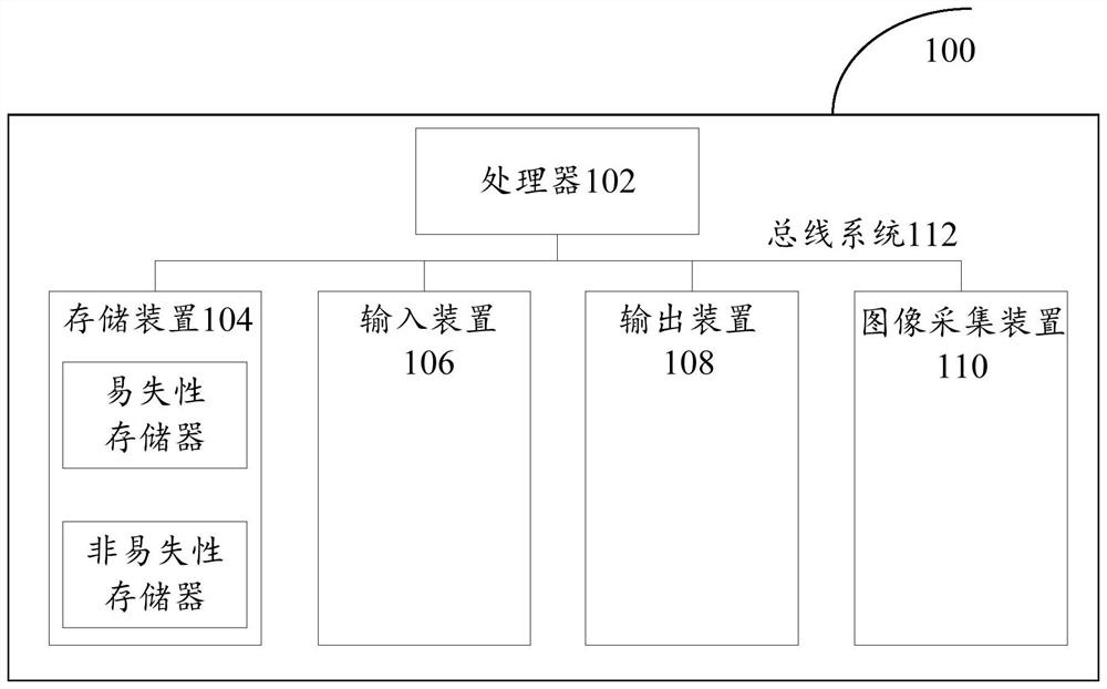
[0031] First, refer to figure 1An example electronic device 100 for implementing the image push method, image acquisition method, device, and image processing system of the embodiments of the present invention will be described.

[0032] like figure 1 Shown is a schematic structural diagram of an electronic device. The electronic device 100 includes one or more processors 102, one or more storage devices 104, an input device 106, an output device 108, and an image acquisition device 110. These components pass through a bus system 112 and / or other forms of connection mechanisms (not shown). It should be noted that figure 1 The components and structure of the electronic device 100 shown are only exemplary, not limiting, and the electronic device may also have other components and structures as required.

[0033] The processor 102 may be a central processing unit (CPU) or other forms of processing units with data processing capabilities and / or instruction execution capabilitie...

Embodiment 2

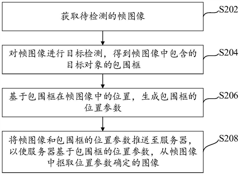
[0040] refer to figure 2 Shown is a flow chart of an image push method applied to an image acquisition device. The method can be executed by the image acquisition device. The image acquisition device can be a mobile phone, a capture recognition machine and other devices. The method specifically includes the following steps:

[0041] Step S202, acquiring a frame image to be detected. The above-mentioned frame image may be a single frame image collected by an image collection device (such as a snapshot recognition machine), or may be multiple frame images in a video stream collected by the image collection device.

[0042] Step S204, performing target detection on the frame image to obtain the bounding box of the target object contained in the frame image. The frame image may contain a target object, and in practical applications, the target object may be other objects such as people, animals, or vehicles.

[0043] In an optional implementation manner, target detection may be...

Embodiment 3

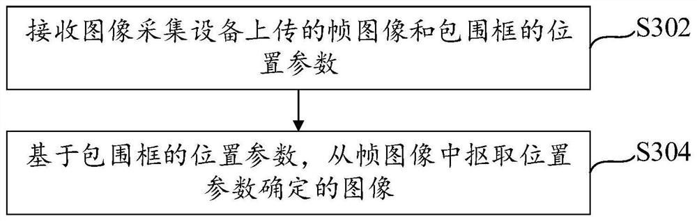
[0060] In conjunction with the foregoing embodiment two, refer to image 3 A flow chart of an image acquisition method applied to a server is shown, the method can be executed by the server, and the server can also be called a background server or a platform server, and the method includes:

[0061] Step S302, receiving the frame image uploaded by the image acquisition device and the location parameters of the bounding box. Wherein, the frame image is at least one frame image collected by the image acquisition device or a frame image extracted from a video stream, and the frame image includes at least one target object. The position parameters of the bounding box are generated by the image acquisition device for target detection on the frame image and based on the detected bounding box containing the target object. The image position parameters include a key point coordinate (x, y) of the bounding box and the bounding box The length value h and width value w.

[0062] Step S30...


PUM


Abstract

The invention provides an image pushing method, an image acquisition method, an image pushing device, an image acquisition device and an image processing system, and relates to the technical field ofimage processing. The image pushing method applied to image acquisition equipment comprises the following steps: acquiring a to-be-detected frame image; Performing target detection on the frame imageto obtain a bounding box of a target object contained in the frame image; Generating position parameters of the bounding box based on the position of the bounding box in the frame image; And pushing the frame image and the position parameter of the bounding box to a server, so that the server pulls out the image determined by the position parameter from the frame image based on the position parameter of the bounding box. According to the invention, the hardware resource occupancy rate and the bandwidth load capacity of the snapshot identification machine can be effectively reduced.

Description

technical field [0001] The present invention relates to the technical field of image processing, in particular to an image pushing method, an image acquisition method, a device and an image processing system. Background technique [0002] The capture recognition machine is a front-end of a smart camera, mainly used to detect target objects such as people and objects from the captured images, extract the images of all target objects contained in the captured images, and then extract all the The images containing the target object (all small images) and the entire captured image are uploaded to the server for storage. However, if an image contains many target objects, the capture recognition machine not only needs to take up a lot of hardware resources to extract multiple small images, but also increases the bandwidth load in the process of pushing multiple small images to the server. Contents of the invention [0003] In view of this, the purpose of the present invention i...

Claims


Application Information

Patent Timeline
Patent Type & Authority Patents(China)
IPC IPC(8): G06F16/583G06F16/51G06T7/11G06T1/20
Inventor 张敬毅周舒畅何蔚然
Owner AXERA SEMICON (SHANGHAI) CO LTD
Why Eureka
Try Eureka