Drill, Cutting Insert, and Method of Manufacturing Cut Product

a technology of cutting inserts and drills, which is applied in the direction of cutting inserts, twist drills, manufacturing tools, etc., to achieve the effect of convenient cross-sectional shape of chips, convenient bending of chips, and easy division

Active Publication Date: 2011-02-24
KYOCERA CORP
View PDF10 Cites 16 Cited by
  • Summary
  • Abstract
  • Description
  • Claims
  • Application Information

AI Technical Summary

Benefits of technology

[0005]An aspect of the present invention is to provide a drill having excellent chip discharge performance and a cutting insert used for the drill.
[0009]According to the drill and the cutting insert, a chip generated by the second cutting edge is curled in a generation direction (a length direction) while making it easy for the cross-sectional shape of the chips to be in a concave shape. This facilitates stable bending of the chip when the chip contacts a machined wall surface of the workpiece. Consequently, the chip is easily divided in the length direction of the chip, and chip discharge performance can be improved by reducing the chip clinging to the holder.
[0010]According to the manufacturing method, the cut product having high finished surface accuracy can be obtained because of using the drill exhibiting excellent chip discharge performance by reducing the chip clinging to the holder.

Problems solved by technology

However, this drill insert has the problem that during cutting process of a very ductile workpiece or the like, a generated chip tends to climb over a breaker groove without being curled, and cling to the drill holder.

Method used


Image

  • Drill, Cutting Insert, and Method of Manufacturing Cut Product
  • Drill, Cutting Insert, and Method of Manufacturing Cut Product
  • Drill, Cutting Insert, and Method of Manufacturing Cut Product

Examples


first preferred embodiment

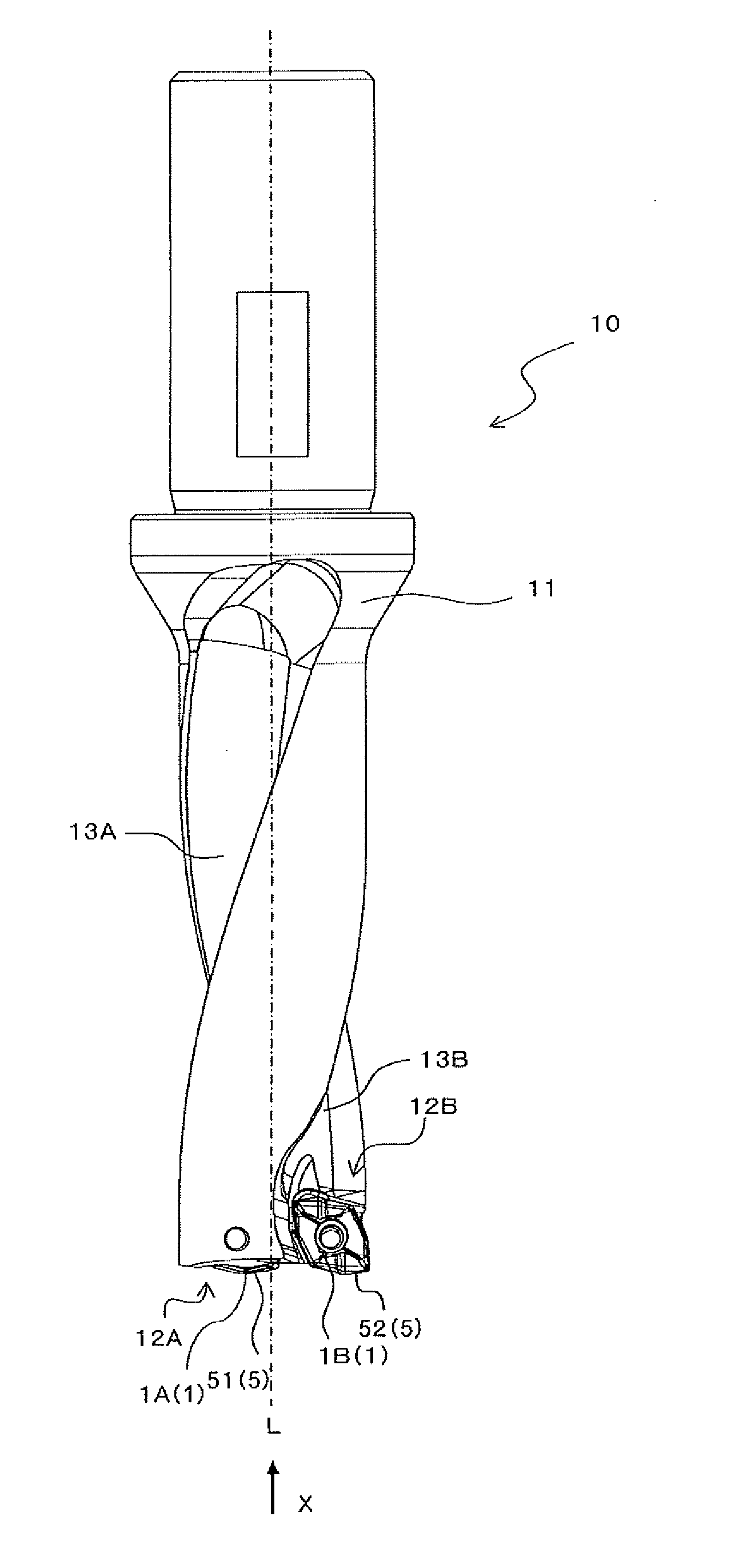
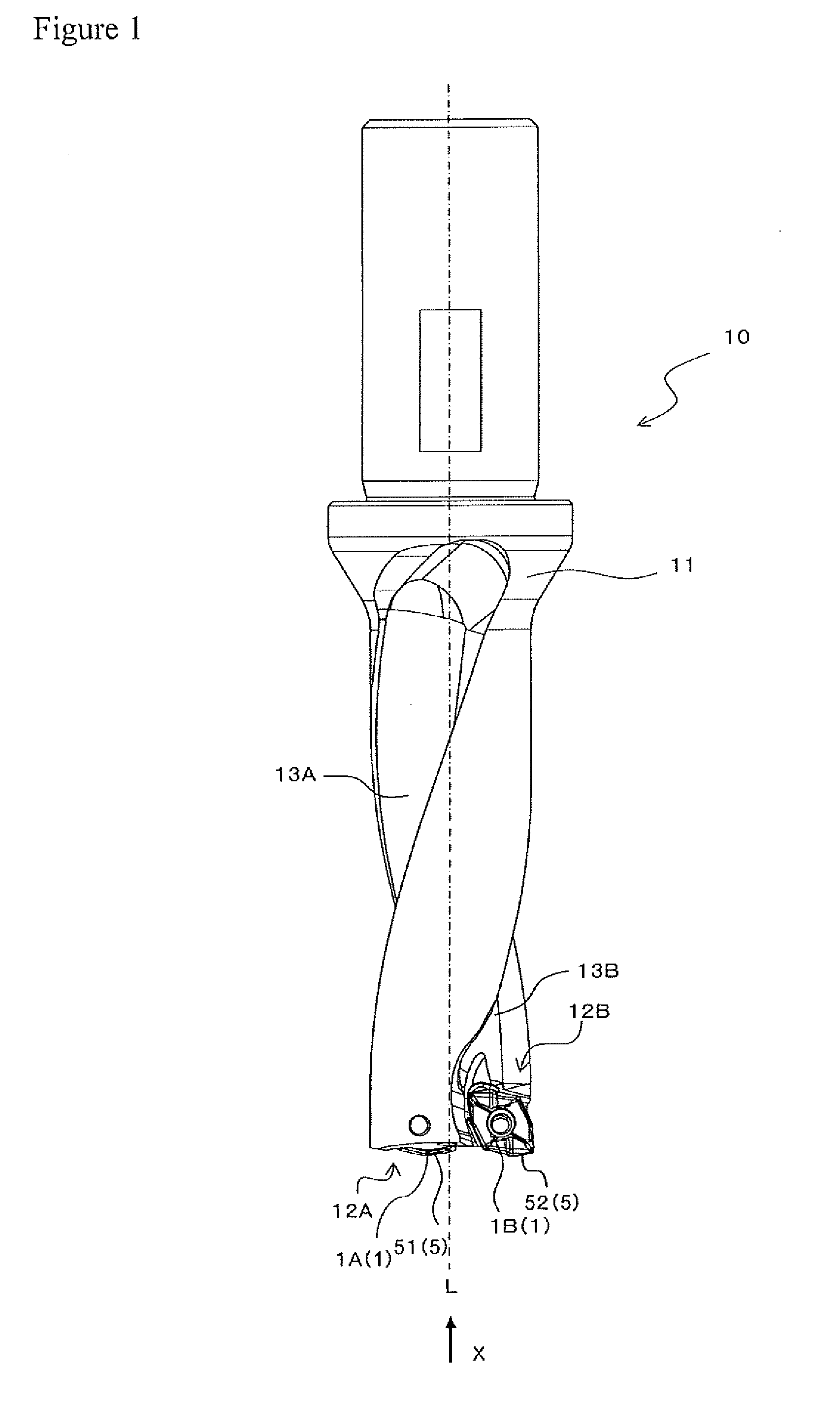
[0023]A drill 10 according to the first embodiment of the present invention is described in detail with reference to FIGS. 1 to 3.

[0024]The drill 10 includes a drill holder 11, and two cutting inserts 1 attached to the front end portion of the drill holder 11.

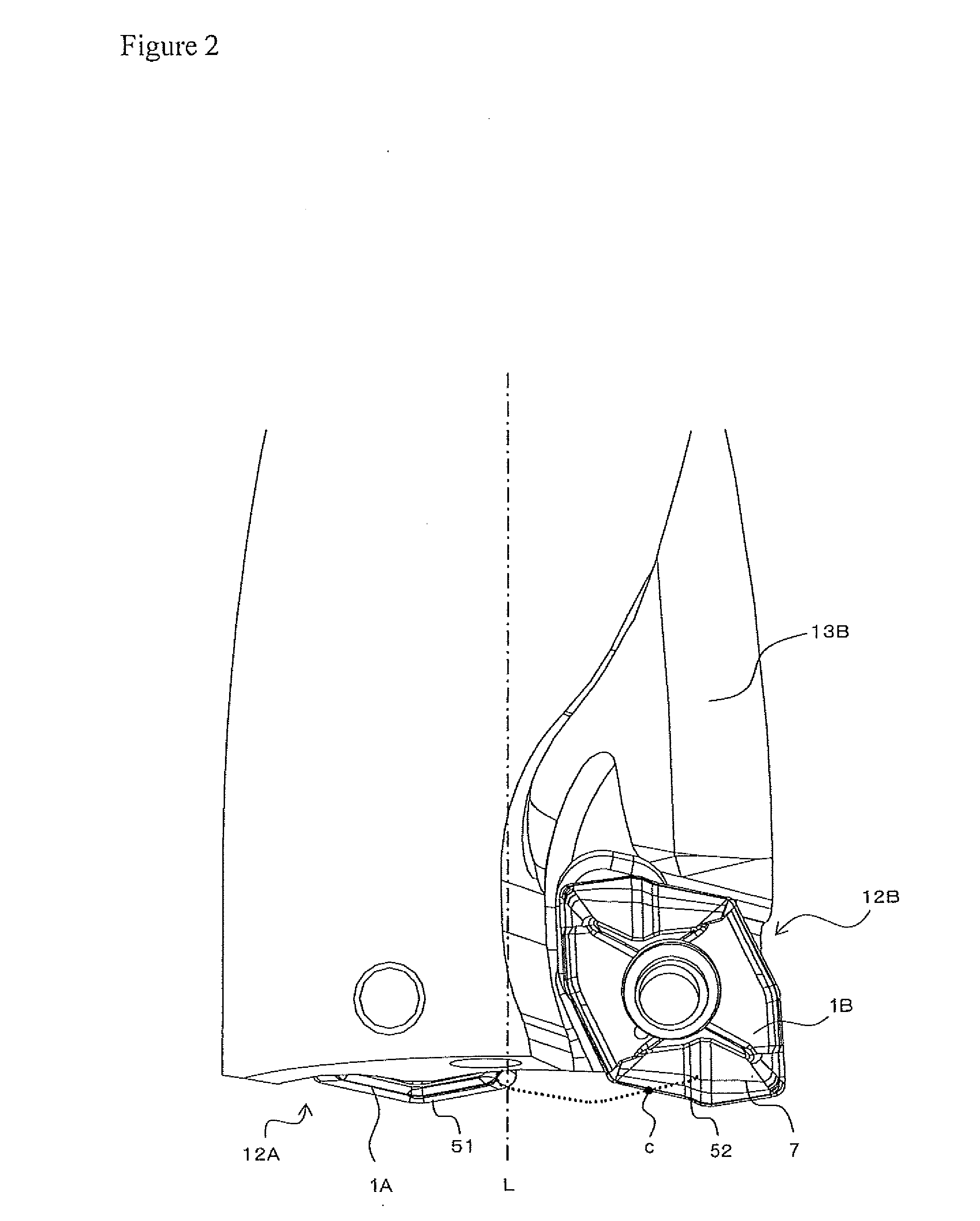
[0025]The drill holder 11 has a substantially columnar shape, for example, a substantially cylindrical shape. The rear end of the drill holder 11 is fixed to a machine tool or a connection member. On the other hand, the drill holder 11 includes, at the front end portion thereof, a first insert pocket 12A placed to pass through the central axis of rotation when viewed from the front end side, and a second insert pocket 12B placed closer to the outer periphery of the drill holder than the first insert pocket 12A. The first insert pocket 12A corresponds to the inner edge insert pocket, and the second insert pocket 12B corresponds to the outer edge insert pocket. The number of the insert pockets may be two or more, and no particula...

second embodiment

[0083]An insert 1′ of a second embodiment according to the present invention is described below in detail with reference to FIGS. 8(a) to 8(c). Similar reference numerals are used to denote the constructions similar to those of the insert 1 of the first embodiment, and the descriptions thereof are omitted.

[0084]Similarly to the insert 1, the insert 1′ of the present embodiment has both of a first cutting edge 51 serving as an inner edge, and a second cutting edge 52 serving as an outer edge so as to be usable as both of a first insert and a second insert.

[0085]The first cutting edge 51 of the present embodiment is formed in a concave shape when viewed from side, and is formed so that at least a part thereof is in the shape of a curved line. With this construction, it is possible to decrease the diameter of chips generated by the first cutting edge 51 whose cross-sectional shape is the concave shape. That is, unlike the second cutting edge 52 functioning as the outer edge, the first ...

third embodiment

[0092]An insert 1″ of a third embodiment according to the present invention is described below in detail with reference to FIGS. 9(a) to 11(d). Similar reference numerals are used to denote the constructions similar to those of the insert 1 of the first embodiment, and the descriptions thereof are omitted.

[0093]Similarly to the insert 1, the insert 1″ of the present embodiment has both of a first cutting edge 51 serving as an inner edge, and a second cutting edge 52 serving as an outer edge.

[0094]In the insert 1″ of the present embodiment, unlike the insert 1 of the first or second embodiment, an upper face 2 does not comprise the convex part 14. That is, as shown in FIGS. 10(a) to 10(c), and FIG. 11(b), a portion of the upper face 2 located at an inner portion of a second breaker groove 7 is connected without level difference from a portion of the upper face 2 connected to the first cutting edge 51. That is, there is no boundary between the portion of the upper face 2 corresponding...


PUM

PropertyMeasurementUnit
width W52aaaaaaaaaaa
width W52caaaaaaaaaa

Abstract

A drill, including: a substantially columnar drill holder including, at a front end portion thereof, a first insert pocket and a second insert pocket formed closer to the outer periphery of the drill holder than the first insert pocket; a first insert which is attached to the first insert pocket and includes a first cutting edge at an intersection of an upper face and a side face; and a second insert which is attached to the second insert pocket and includes a second cutting edge at an intersection of a upper face and a side face. The first insert pocket is located passing through a central axis of rotation of the drill holder. The second cutting edge has a concave shape when viewed from the front end side of the drill holder, and has a curved line at least a part thereof.

Description

TECHNICAL FIELD[0001]The present invention relates to a drill and a cutting insert used for the drill.BACKGROUND ART[0002]A throwaway drill has heretofore been used as a tool for drilling a workpiece such as metals or the like. In this drill, an inner edge insert with a cutting edge (inner edge) for cutting an inner peripheral portion of a lower face of a hole, and an outer edge insert with a cutting edge (outer edge) for cutting an outer peripheral portion of the lower face of the hole are detachably attached to a front end portion of a substantially cylindrical drill holder. The inner edge insert is placed on the central axis of rotation side, and the outer edge insert is placed on the outer peripheral side of the drill holder. For example, patent document 1 discloses a drill insert whose inner edge and outer edge are linear.[0003]However, this drill insert has the problem that during cutting process of a very ductile workpiece or the like, a generated chip tends to climb over a b...

Claims


Application Information

Patent Timeline
Patent Type & Authority Applications(United States)
IPC IPC(8): B23B51/02B23B27/16B23B35/00
CPCB23B27/145B23B51/048B23B2200/085B23B2200/202Y10T408/906B23B51/02Y10S408/713Y10T408/9098Y10T408/89Y10T408/04B23B51/00
Inventor ISHI, HIROHISA
Owner KYOCERA CORP
Why Eureka
Try Eureka