Method and facility for recovering co2 gas in cement manufacturing facility

a technology of cement manufacturing facility and co2 gas, which is applied in the direction of lighting and heating apparatus, separation processes, furniture, etc., can solve the problems of difficult recovery, high cost of separating and recovering co2 gas, etc., and achieve the effect of effectively using the heat sour

Inactive Publication Date: 2011-02-24
MITSUBISHI MATERIALS CORP
View PDF2 Cites 12 Cited by
  • Summary
  • Abstract
  • Description
  • Claims
  • Application Information

AI Technical Summary

Benefits of technology

[0018]The present invention has been made in view of the above described circumstances. An object of the present invention is to provide a method and facility for recovering CO2 gas in a cement manufacturing fa...

Problems solved by technology

Thus, in spite of the fact that the discharge amount of CO2 is large, there is a problem that the CO2 gas has a concentration of about 30 to 35% and hence is difficult to be recovered.
However, the methods have a problem that the cost for recovering CO2 gas is still very high.
However, in this method, the cost for separating and recovering CO2 is high, and hence this method is not realized for the same reason as that for the above described methods.
For this reason, when after limestone is calcined by the prior art based on the indirect heating type limestone burning furnace, cement clinker is a...

Method used


Image

  • Method and facility for recovering co2 gas in cement manufacturing facility
  • Method and facility for recovering co2 gas in cement manufacturing facility
  • Method and facility for recovering co2 gas in cement manufacturing facility

Examples


first embodiment

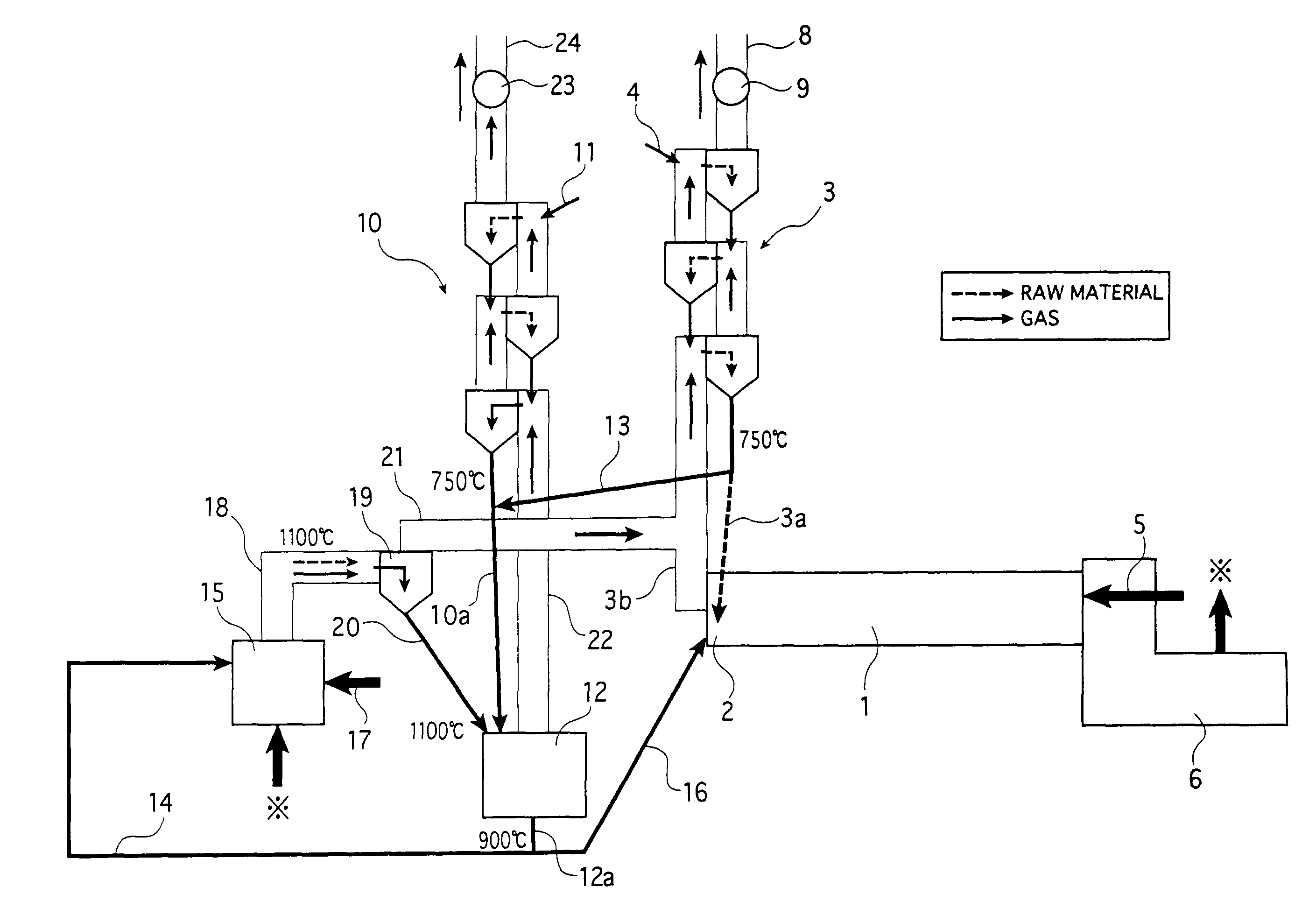
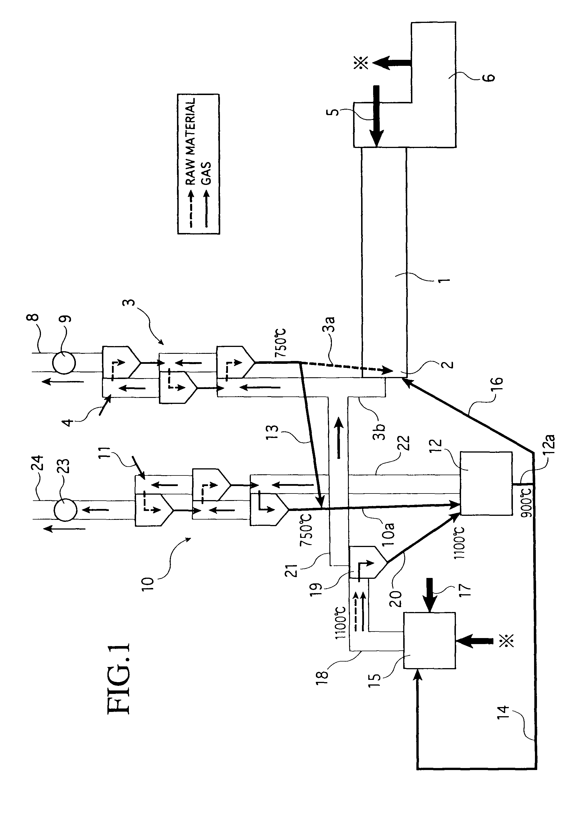
[0091]FIG. 1 shows a first embodiment of a CO2 gas recovery facility in a cement manufacturing facility according to the present invention, in which the configuration of the cement manufacturing facility is the same as that shown in FIG. 12. Thus, in FIG. 1, the same components as those in FIG. 12 are denoted by the same reference numerals and characters, and the explanation thereof is simplified. In FIG. 1, reference numeral 10 denotes a second preheater provided independently of the preheater (first preheater) 3 of the cement manufacturing facility.

[0092]The second preheater 10 is configured by a plurality of stages of cyclones arranged in series in the vertical direction similarly to the preheater 3, and is configured such that the cement material is fed to the uppermost cyclone from a feed line 11. Further, the upper end of a transfer pipe 10a is connected to the bottom part of the lowermost cyclone of the second preheater 10. The lower end of the transfer pipe 10a is introduced...

second embodiment

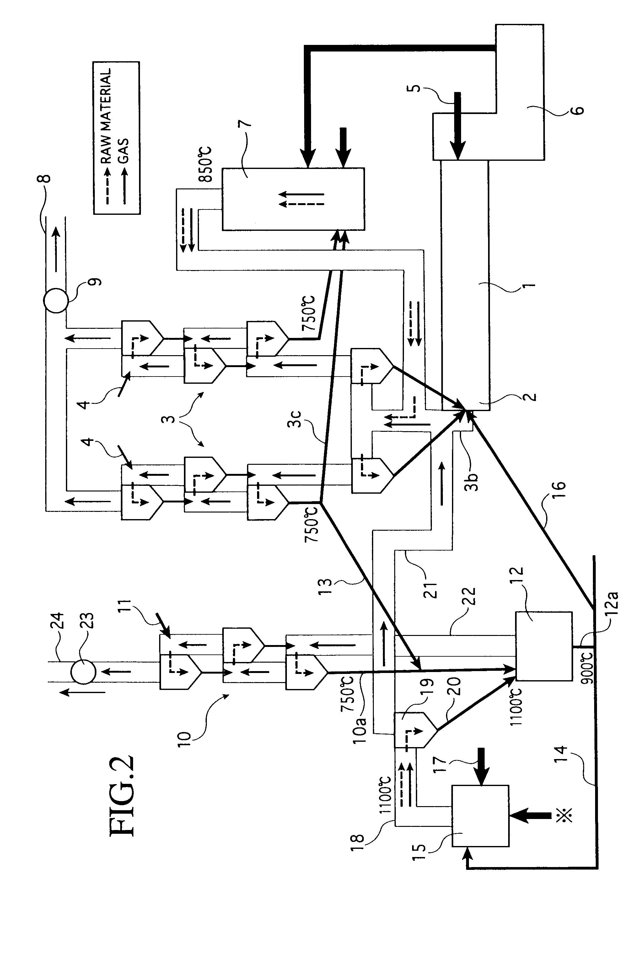
[0099]FIG. 2 shows a second embodiment of CO2 gas recovery facility according to the present invention. The same components as those shown in FIG. 1 are denoted by the same reference numerals and characters, and the explanation thereof is simplified.

[0100]The recovery facility is configured in such a manner that the existing cement manufacturing facility shown in FIG. 12 is used as it is, and that the recovery facility is added to the cement manufacturing facility.

[0101]That is, in this recovery facility, the extraction line 13 for sending the cement material from the preheater 3 of the cement manufacturing facility to the mixer / calciner 12 is branch-connected to a transfer pipe 3c for sending the cement material to the calciner 7 from the second stage cyclone from the bottom of the preheater 3. Thereby, the cement material before calcination preheated in the preheater 3 is introduced to the mixer / calciner 12.

[0102]Next, there will be described an embodiment of a CO2 gas recovery me...

third embodiment

[0118]FIG. 8 shows a schematic configuration of a third embodiment of a CO2 gas recovery facility in a cement manufacturing facility according to the present invention.

[0119]In FIG. 8, reference numeral 110 denotes a second preheater provided independently of a preheater (first preheater) 103 of a cement manufacturing facility.

[0120]The second preheater 110 is configured by a plurality of stages of cyclones arranged in series in the vertical direction similarly to the preheater 103, and is configured such that the cement material is fed to the uppermost cyclone from a feed line 111. Further, the upper end of a transfer pipe 110a is connected to the bottom part of the lowermost cyclone of the second preheater 110, and the lower end of the transfer pipe 110a is introduced into a mixer / calciner 112.

[0121]On the other hand, in the preheater 103 of the cement manufacturing facility, an extraction line 113 for extracting the cement material before calcination is connected to a transfer pi...


PUM

PropertyMeasurementUnit
Temperatureaaaaaaaaaa
Concentrationaaaaaaaaaa

Abstract

To provide a method and facility for enabling CO2 gas generated in a cement manufacturing facility to be separated and recovered at a high concentration. To this end, according to the present invention, the calcination of a cement material and the recovery of CO2 gas generated in a calciner are performed by one of the following steps of: [1] superheating the cement material before calcination to at least the calcination temperature thereof in a superheating furnace and then mixing the superheated cement material with a new cement material before calcination in a mixer/calciner; [2] mixing, in the mixer/calciner, the cement material before calcination with a part of high-temperature cement clinker discharged from a cement kiln; and [3] using an externally heated calciner.

Description

TECHNICAL FIELD[0001]The present invention relates to a method and facility for recovering, in high-concentration, CO2 gas mainly generated at the time of calcination of a cement material in a cement manufacturing facility.BACKGROUND ART[0002]In recent years, attempts for reducing carbon dioxide (CO2) gas, which is a main cause of the global warming phenomenon, have been made worldwide and in all industries.[0003]The cement industry, together with the electric power industry, the steel industry, and the like, is one of the industries which discharge a large amount of CO2 gas. The discharge amount of CO2 gas of the cement industry is about 4% of the total amount of CO2 gas discharged in Japan. For this reason, the reduction in the amount of CO2 gas discharged in the cement industry greatly contributes to the reduction in the total amount of CO2 gas discharged in Japan.[0004]FIG. 12 shows a common cement manufacturing facility in the cement industry. In the figure, reference numeral 1...

Claims


Application Information

Patent Timeline
IPC IPC(8): C01B31/20B01D17/00C01B32/50
CPCB01D2257/504C04B7/367F27D17/008F27B7/2041C04B7/44Y02P40/18
Inventor SHIMA, HIROKAZUMOTOHASHI, EIICHIWANG, JUNZHUTAKAYAMA, YOSHINORI
Owner MITSUBISHI MATERIALS CORP
Why Eureka
Try Eureka