Drive control method, drive control apparatus, stage control method, stage control apparatus, exposure method, exposure apparatus and measuring apparatus

Inactive Publication Date: 2011-02-24
NAT UNIV CORP YOKOHAMA NAT UNIV +1
View PDF18 Cites 12 Cited by
  • Summary
  • Abstract
  • Description
  • Claims
  • Application Information

AI Technical Summary

Benefits of technology

[0026]According to the seventh aspect, since the stage is driven using the stage control apparatus which can prevent the adverse effect of the vibration of the stage generated after the stage is accelerated in the fir

Problems solved by technology

However, when a large-sized stage is accelerated, the stage easily vibrates and the vibration remains even after the accelerated stage reaches

Method used


Image

  • Drive control method, drive control apparatus, stage control method, stage control apparatus, exposure method, exposure apparatus and measuring apparatus
  • Drive control method, drive control apparatus, stage control method, stage control apparatus, exposure method, exposure apparatus and measuring apparatus
  • Drive control method, drive control apparatus, stage control method, stage control apparatus, exposure method, exposure apparatus and measuring apparatus

Examples


Embodiment Construction

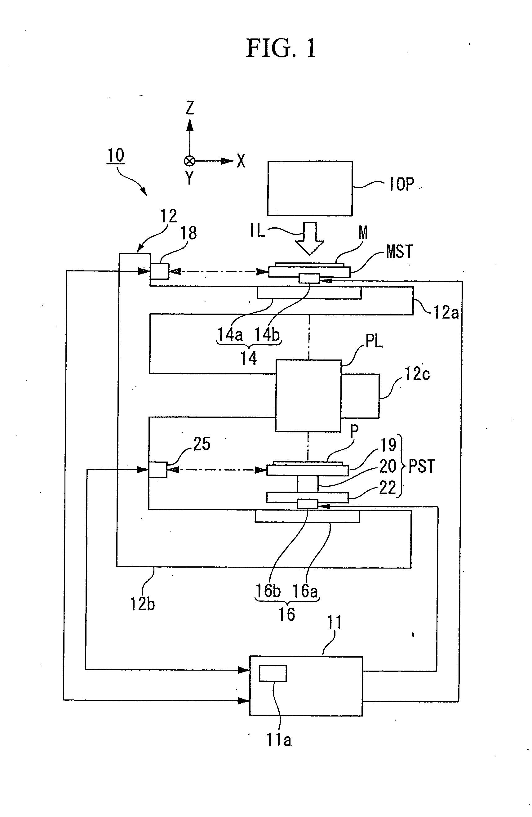
[0033]Hereinafter, an embodiment of the invention will be described with reference to the accompanying drawings. FIG. 1 is a diagram schematically illustrating the configuration of an exposure apparatus 10 according to an embodiment of the invention. The exposure apparatus 10 is an equal-magnification collective transfer type liquid crystal scanning exposure apparatus that scans a mask M having a liquid crystal display device pattern formed thereon and a glass plate (hereinafter, referred to as “plate”) P as a plate (and object) held on a plate stage PST as a first stage at the same speed in a first direction, that is, a predetermined scanning direction (which is the X axis direction (lateral direction in the paper surface) of FIG. 1, relative to a projection optical system PL and transfers the pattern formed on the mask M to the plate P.

[0034]The exposure apparatus 10 includes an illumination system IOP that illuminates a predetermined slit-like illumination area (a rectangular or ...


PUM


Abstract

A drive control method of controlling an object which can move at least in a first direction and a second direction different from the first direction is provided. Here, a force applied to the object is controlled on the basis of a driving signal for driving a first actuator moving the object in the first direction and a disturbance correcting signal generated from a disturbance signal in the second direction at an output terminal of the object.

Description

CROSS-REFERENCE TO RELATED APPLICATION[0001]This is a Continuation Application of International Application No. PCT / JP2008 / 066086, filed Sep. 5, 2008, which claims priority to Japanese Patent Application No. 2007-233325, filed on Sep. 7, 2007, the contents of which are incorporated herein by reference.BACKGROUND[0002]1. Field of the Invention[0003]The present invention relates to a drive control method, a drive control apparatus, a stage control method, a stage control apparatus, an exposure method, an exposure apparatus, and a measuring apparatus.[0004]2. Description of Related Art[0005]So far, in the process of manufacturing a liquid crystal display (generically referred to as “flat panel display”), an exposure apparatus has often been used to form elements such as transistors or diodes on a plate (glass plate). In the exposure apparatus, a plate to which a resist is applied is placed on a holder of a stage device and a fine circuit pattern drawn on a mask is transferred to the pl...

Claims


Application Information

Patent Timeline
IPC IPC(8): G01M1/38
CPCF16F15/002G03F7/70525G03F7/709G03F7/70758G03F7/70725G03F7/20H01L21/0277H01L21/681
Inventor FUJIMOTO, HIROSHISAKATA, KOICHISAIKI, KAZUAKIOHTOMO, TAKESHI
Owner NAT UNIV CORP YOKOHAMA NAT UNIV
Why Eureka
Try Eureka