Micromechanical component

a micro-mechanical and component technology, applied in the direction of turning-sensitive devices, instruments, manufacturing tools, etc., can solve the problems only possible implementation of small precise distance between stop and seismic mass, and large manufacturing complexity

Active Publication Date: 2011-03-03
ROBERT BOSCH GMBH
View PDF15 Cites 56 Cited by
  • Summary
  • Abstract
  • Description
  • Claims
  • Application Information

AI Technical Summary

Benefits of technology

[0007]An object of the present invention is to provide an improved micromechanical component having a stop structure. It is a further object of the present invention to provide an improved method for manufacturing a micromechanical component having a stop structure.

Problems solved by technology

In conventional components, the problem exists that a stop structure may only be situated relatively imprecisely in relation to a seismic mass.
The implementation of a small, precisely defined distance between stop and seismic mass is therefore only possible with a relatively great manufacturing complexity or not at all.
Further disadvantages may be that limiting the deflection of a seismic mass is only possible “suddenly,” and a stop structure possibly has an undetermined electrical potential, whereby a reliable operation of a component may be impaired.

Method used


Image

  • Micromechanical component
  • Micromechanical component
  • Micromechanical component

Examples


Embodiment Construction

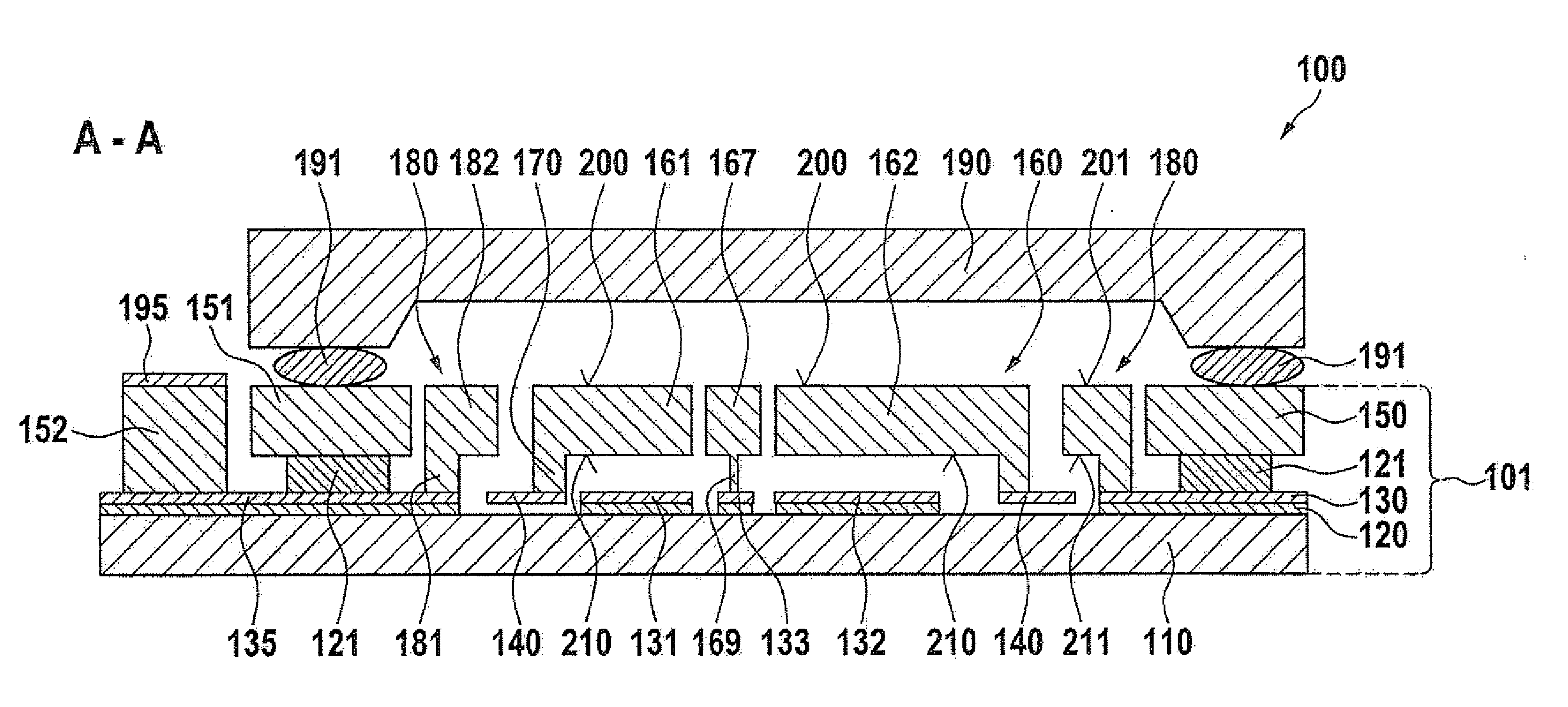
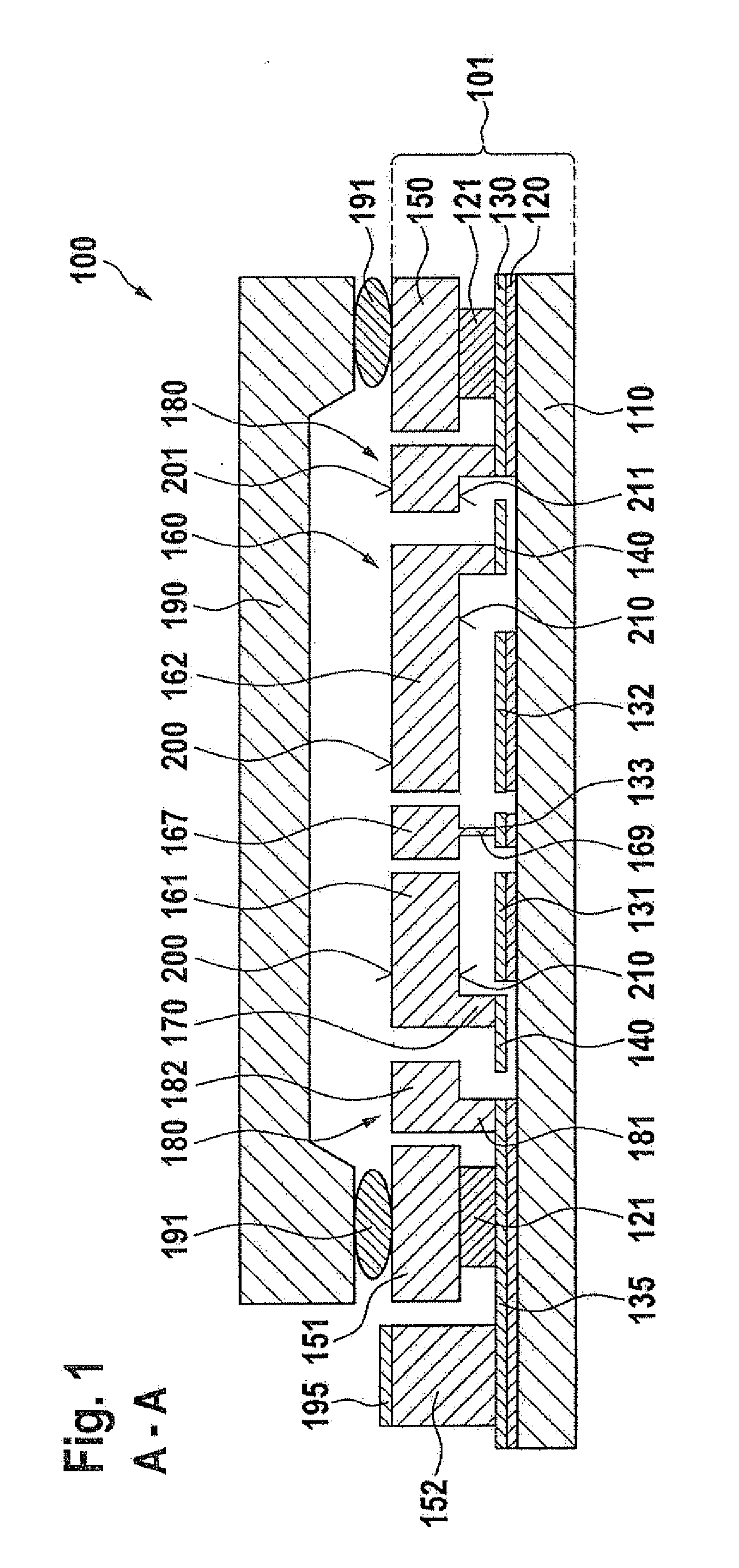
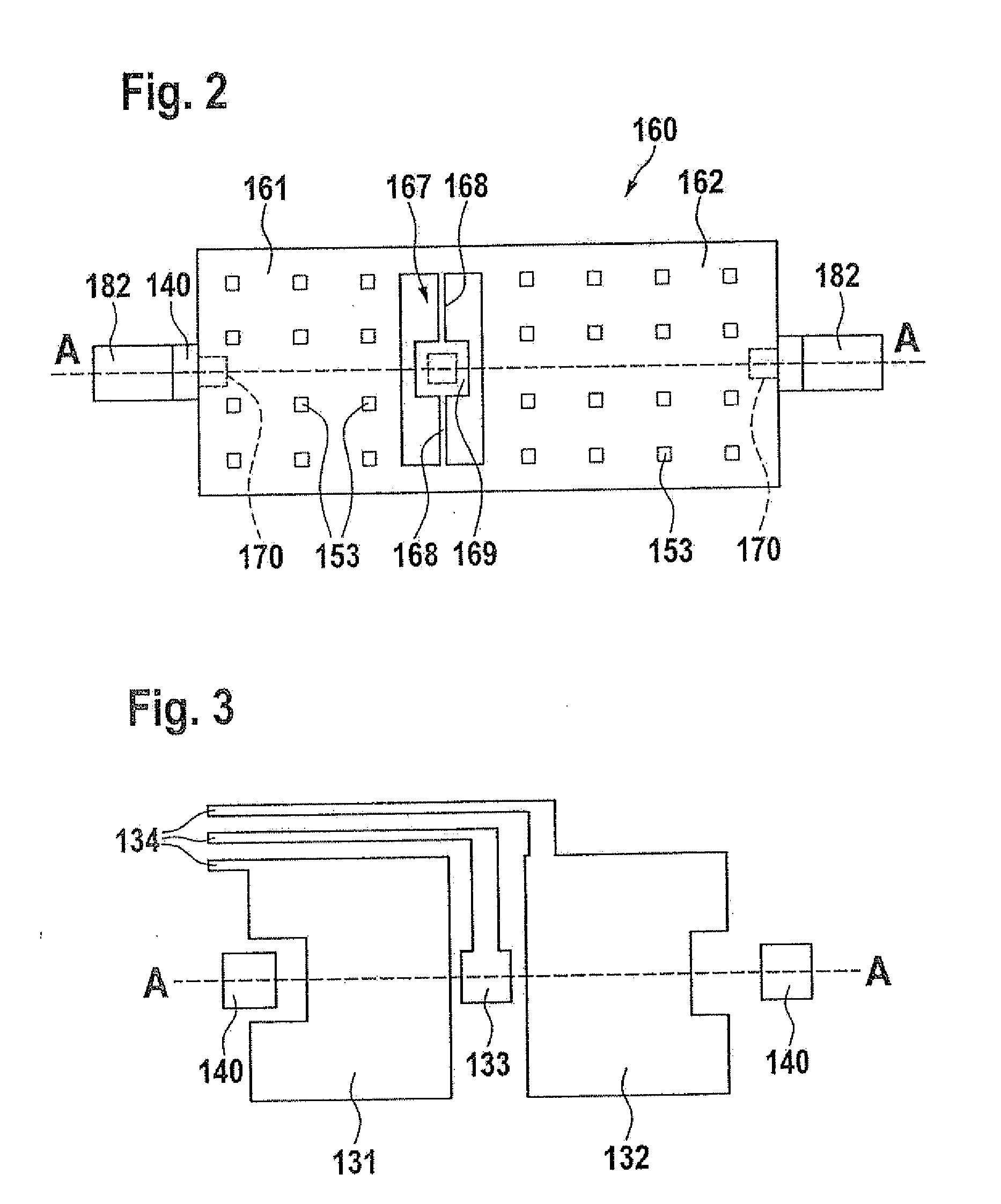
[0035]The micromechanical components which are described on the basis of the figures, and which are also referred to as “Z sensors,” have a seismic mass, which is situated on a substrate, in the form of a rotatable rocker structure having two lever arms. To limit a deflection of a lever arm of the seismic mass in a direction away from the substrate, the components further have an associated stop structure, which is separate from the seismic mass, and which is situated with high precision and at a defined (small) distance in relation to the seismic mass. Furthermore, possible advantageous methods for manufacturing the components are described. In this manner, for example, components may be implemented in which the freedom of movement of a seismic mass is limited to (significantly) less than 2 μm.

[0036]FIGS. 1 through 3 show a micromechanical component 100 in various schematic views, FIG. 1 including a lateral sectional view and FIGS. 2 and 3 including top views of parts of component ...


PUM

PropertyMeasurementUnit
freedom of movementaaaaaaaaaa
distanceaaaaaaaaaa
thicknessaaaaaaaaaa

Abstract

A micromechanical component which has a substrate, a seismic mass, which is deflectably situated on the substrate, and a stop structure for limiting a deflection of the seismic mass in a direction away from the substrate. The stop structure is situated on the substrate and has a limiting section for limiting the deflection of the seismic mass, which is in a plane with the seismic mass. Furthermore, a method for manufacturing a micromechanical component is described.

Description

CROSS REFERENCE[0001]The present application claims the benefit under 35 U.S.C. §119 of German Patent Application No. 102009029095.8 filed on Sep. 2, 2009, which is expressly incorporated herein by reference in its entirety.FIELD OF THE INVENTION[0002]The present invention relates to a micromechanical component, which has a substrate, a seismic mass which is deflectably situated on the substrate, and a stop structure for delimiting a deflection of the seismic mass in a direction away from the substrate.BACKGROUND INFORMATION[0003]Micromechanical components, which are used, for example, in the automobile field as acceleration sensors, typically have a movable microstructure. The microstructure, which is also referred to as an MEMS structure (micro-electromechanical system), frequently includes a seismic mass (oscillating mass), which is suspended on a substrate via spring elements. In this case, an acceleration acting on the substrate results in a deflection of the seismic mass in re...

Claims


Application Information

Patent Timeline
Patent Type & Authority Applications(United States)
IPC IPC(8): G01C19/56B23P17/04
CPCB81B3/0051G01P15/0802B81B2201/025G01P15/125Y10T29/49826G01P2015/0831
Inventor REINMUTH, JOCHEN
Owner ROBERT BOSCH GMBH
Why Eureka
Try Eureka