Method and device for producing a surface structure for a metallic press plate, endless belt or embossing roller

a technology of endless belts and embossing rollers, which is applied in the manufacture of presses, laser beam welding apparatuses, and manufacturing tools. it can solve the problems of difficult to ensure the reproducibility of applying the mask required for obtaining high imaging precision, difficult to control the position of lasers and/or focusing devices, and difficult to achieve the effect of adapting and correcting laser beams

Active Publication Date: 2011-03-03
HUECK RHEINISCHE
View PDF12 Cites 24 Cited by
  • Summary
  • Abstract
  • Description
  • Claims
  • Application Information

AI Technical Summary

Benefits of technology

[0049]In order to avoid problems in the boundary portions of the respective portions, wherein the problems can occur for example due to imprecision in the support of the press plate or in the support of the slide of the laser assembly, it is furthermore provided not to align the portions at right angles relative to one another, but to provide them with curved boundary portions, which are advantageously optimized, so that this portion of the surface of the press plate or the endless belt contacts surface portions which are not processed by the laser at all or only processed minimally. Thus, possible edge problems in the boundary portions can be prevented, which leads to a detailed true reproduction of the surface structure. This method is always desirable when large structures shall be processed which extend over an essential portion of the press plate or endless belt and which have to be divided into different particular portions.
[0050]In another embodiment of the invention it is provided that measurement points are provided on the surface, which facilitate continuous control of the laser and / or focusing device position, so that adapting and correcting of the laser beam is facilitated through the control device. The measurement points provided on the surface can be detected through an auxiliary laser or another position measuring method and can be used for correcting the laser beam orientation. Thus there is the option to perform ongoing corrections of the laser beam also for large format press plates, endless bands and embossing rollers and to maintain an exact position also over a large surface area.

Problems solved by technology

The reproducibility of the masks produced in this manner is problematic, because the negative or positive image always has to be positioned in an exactly identical position relative to the photosensitive layer in order to expose the light sensitive layer, when more than one exposing and etching process shall be performed after the other, in order to thus apply complex 3D structures to the surface of a press plate or endless belt.
This is problematic in particular when the negative or positive image is directly applied to the light sensitive layer in order to expose the light sensitive layer, and the negative or positive image does not have exactly the same distance at each position of the photosensitive layer.
The reproducibility of applying the mask required for obtaining high imaging precision is thus not always assured, in particular for a photographic method.
Additional problems can be created when a 3D structure shall be achieved through plural exposing and etching processes required in sequence, and thus plural masks have to be applied for this purpose after one another in sequence, wherein an etching process is performed between each mask application.
Through the precise positioning and the required number of respective masks, thus the production of the press plates or of the endless belts is very complex and expensive.
However, also for this method, numerous etching processes are used, which are detrimental to the environment.

Method used


Image

  • Method and device for producing a surface structure for a metallic press plate, endless belt or embossing roller
  • Method and device for producing a surface structure for a metallic press plate, endless belt or embossing roller
  • Method and device for producing a surface structure for a metallic press plate, endless belt or embossing roller

Examples


Embodiment Construction

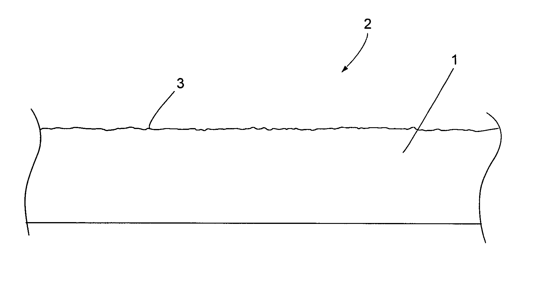
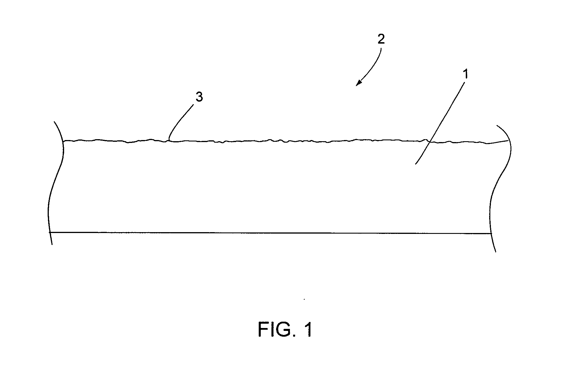
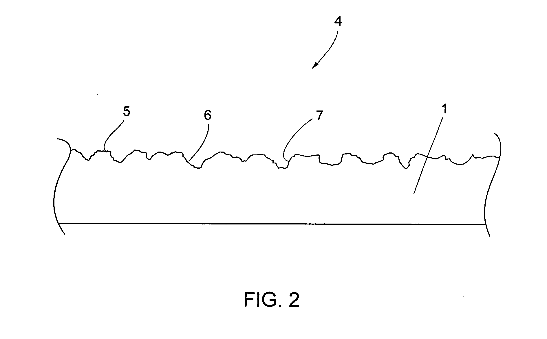
[0066]FIG. 1 illustrates a press plate 1 partial cross sectional view, wherein the press plate is typically made from metal. The surface 2 to be processed includes a surface roughness 3 before processing, wherein the surface roughness is typical for the manufacturing process. After pre cleaning of the press plate 1 has been performed, a surface structure 4 is generated through the laser method according to the invention, wherein the surface structure is characterized by high portions 5 and low portions 6 according to FIG. 2. The high portions 5 and also the low portions 6 furthermore include fine structuring 7. The entire structuring of the surface of the press plate 1 is thus generated through the laser method according to the invention, wherein a depth focusing of the laser beam is performed through respective controlling of the focusing device (laser optics). Furthermore, a detection of a particular portion of the press plate is performed through the focusing device in order to p...


PUM

PropertyMeasurementUnit
depthaaaaaaaaaa
diameteraaaaaaaaaa
repeat frequencyaaaaaaaaaa

Abstract

A method for producing a surface structure for a metallic press plate, endless belt or a cylindrical embossing roller through at least one laser and a device for using the method. In order to provide a cost effective production for the surface structure while using environmentally friendly techniques, it is proposed to use a laser which produces the entire surface structure through partial removal of a surface of a metallic press plate, endless belt or embossing roller to be processed. Thus, the laser is controlled by a provided 3D topography, wherein control of the laser is performed through obtained x, y and z coordinates in order to produce a depth structure, so that high portions and low portions are formed.

Description

RELATED APPLICATIONS[0001]This patent application claims priority from and incorporates by reference European patent application 09 010 921.6 filed on Aug. 26, 2009.FIELD OF THE INVENTION[0002]The invention relates to a method for producing a surface structure for a metal press plate, endless belt or cylindrical embossing roller using at least one laser. The invention also relates to a device for performing the method.BACKGROUND OF THE INVENTION[0003]Press plates or endless belts are being used for producing material sheets, for example wood material sheets, which are provided with a respective decorative design. Alternative applications can be found in the production of laminate panels or laminate floor plates. The material sheets employed include a core made from MDF or HDF, wherein different material layers are applied at least on one side, wherein the material layers can included for example a decorative layer and a protective overlay layer. In order to prevent warping of the ma...

Claims


Application Information

Patent Timeline
Patent Type & Authority Applications(United States)
IPC IPC(8): B30B5/04B23K26/04
CPCB23K26/0084B23K26/0884B23K26/365B44C1/228B44B5/026B23K26/361B23K26/355B30B15/062B30B3/005B30B5/04B23K26/362
Inventor ESPE, OLIVERESPE, ROLF
Owner HUECK RHEINISCHE
Why Eureka
Try Eureka