Separation device of ejector motor for portable missile

a portable missile and ejector motor technology, applied in the direction of rocket launchers, weapons, projectiles, etc., can solve the problems of excessive impulsive shock, high device cost, and inability to separate the ejector motor from the ejector motor, and achieve the effect of simplifying the structur

a portable missile and ejector motor technology, applied in the direction of rocket launchers, weapons, projectiles, etc., can solve the problems of excessive impulsive shock, high device cost, and inability to separate the ejector motor from the ejector motor, and achieve the effect of simplifying the structur

US20110048267A1Active Publication Date: 2011-03-03AGENCY FOR DEFENSE DEV

Image

  • Separation device of ejector motor for portable missile
  • Separation device of ejector motor for portable missile
  • Separation device of ejector motor for portable missile

Examples


Embodiment Construction

[0025]Description will now be given in detail of the present invention, with reference to the accompanying drawings.

[0026]Hereinafter, a separation device of an ejector motor for a portable missile according to the present invention will be explained in more detail with reference to the attached drawings.

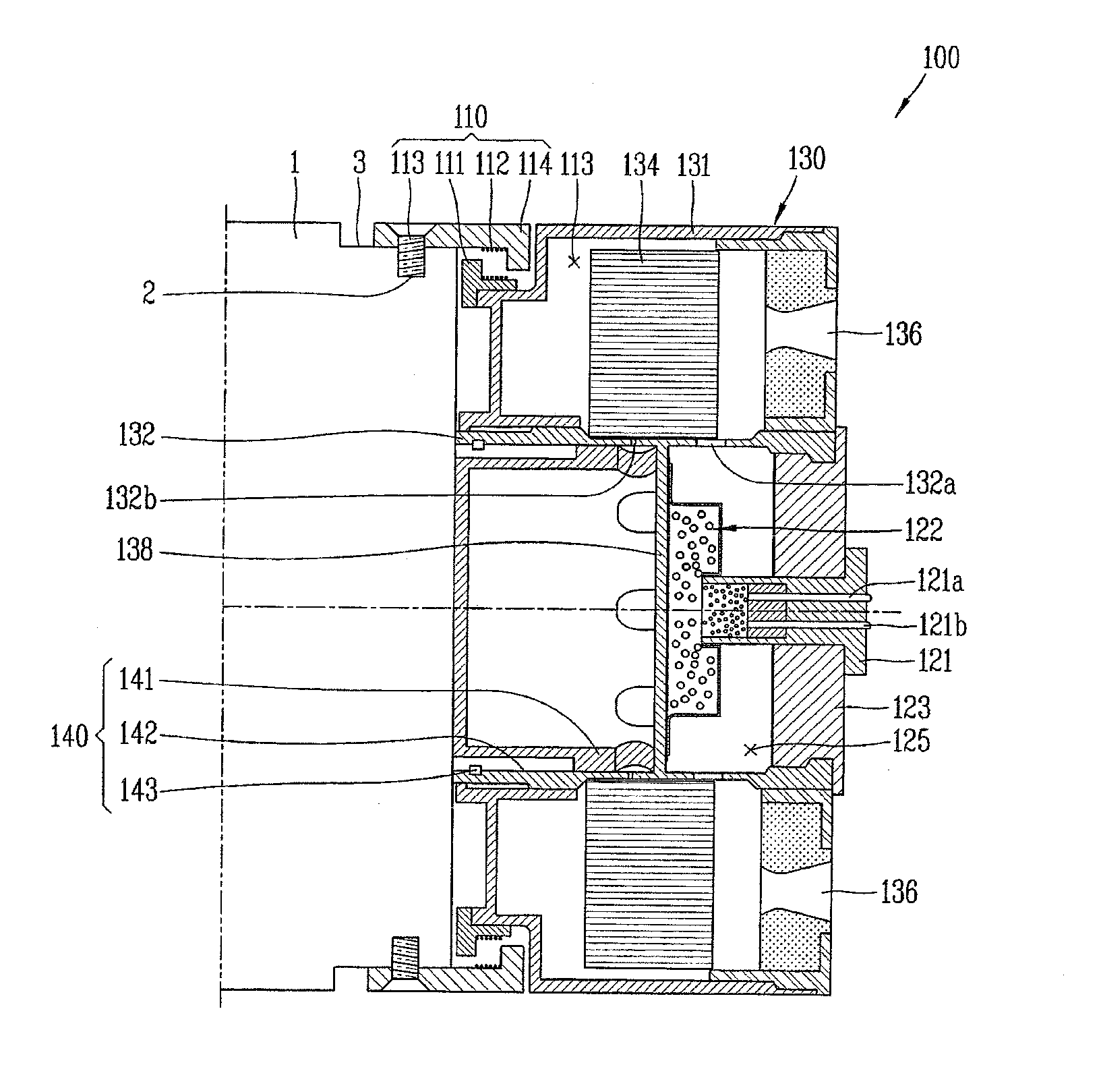
[0027]A distinguishing characteristic of this invention is that ejection and separation can be performed with an one-body device by selecting a unique ring shape structure. The outer part consist of an ejection rocket motor, and the inner part consist of a separation system using a piston and a separation cylinder. The ejection of a missile is performed by a thrust generated by the rocket motor, and the separation is performed by cutting off shearing bolts using a force generated by the separation cylinder when the rocket motor is burned completely. These kinds of operation method and structure allow a volume and weight of the separation device to be minimized.

[0028]FIG. 1 is a sect...


PUM


Abstract

Disclosed is a separation device of an ejector motor for a portable missile, capable of being separated from a missile without any additional separation devices after ejecting the missile. An ejection rocket motor and a separation device are integrally formed. Ejection is performed by a thrust generated while the ejection rocket motor is combusted, and separation is performed by cutting off shearing bolts with using a force generated from a separation cylinder when the combustion of the ejection rocket motor has been completed. This operation and configuration may minimize a weight and a space occupied by a general ejection and separation device in a missile system.

Description

CROSS-REFERENCE TO A RELATED APPLICATION[0001]Pursuant to 35 U.S.C. ยง119(a), this application claims the benefit of earlier filing date and right of priority to Korean Application 10-2009-0083186, filed on Sep. 3, 2009, the content of which is incorporated by reference herein in its entirety.BACKGROUND OF THE INVENTION[0002]1. Field of the Invention[0003]The present invention relates to a separable ejection device, and particularly, to a separation device of an ejector motor for a portable missile.[0004]2. Background of the Invention[0005]In general, a tactical missile is mounted inside a lunch tube and comes out of it according to a firing signal. Especially in a man-portable missile, exhaust plume of a rocket motor can hurt a gunner during the firing process, due to a short distance between the man-portable missile and the gunner. To eliminate the possibility, it is conventional to ignite the rocket motor after the missile is ejected and moved to a fixed distance away from the lau...

Claims


Application Information

Patent Timeline
03 Mar 2011
Publication
US20110048267A1
IPC
F42B15/36
CPC
F42B15/36; F41F3/04; F42B15/38
Inventors
LEE, HYO-NAM; OH, JONG-YUN