Hydrogen exhaust system for fuel cell vehicle

a fuel cell and exhaust system technology, applied in the field of fuel cell systems, can solve the problems of affecting the performance of the fuel cell stack, clogging the flow field to impede the migration, and reducing so as to minimize the possibility of explosion, ensure the silence of the vehicle, and maximize the safety of the vehicl

Active Publication Date: 2011-03-03
HYUNDAI MOTOR CO LTD
View PDF4 Cites 29 Cited by
  • Summary
  • Abstract
  • Description
  • Claims
  • Application Information

AI Technical Summary

Benefits of technology

[0018]The present invention preferably provides a hydrogen exhaust system for a fuel cell vehicle, which is suitably configured to actively control an exhaust path of hydrogen discharged from an anode of a fuel cell stack to suitably maximize the safety of the vehicle by minimizing the possibility of explosion due to hydrogen exhaust and ensure the silence of the vehicle by suitably minimizing noise generated during hydrogen exhaust.

Problems solved by technology

Accordingly, the nitrogen reduces the partial pressure of hydrogen to suitably degrade the performance of the fuel cell stack, and the product water clogs flow fields to impede the migration of hydrogen.
Preferably, the hydrogen discharged during the anode purge may cause a problem.
When the concentration of hydrogen discharged from the anode is high, there is a risk of explosion.
In certain examples where the diluter is used, the hydrogen is only mixed with air and discharged, but the absolute amount of hydrogen is not suitably reduced.
Accordingly, when the fuel cell system is while the vehicle is stopped or travels at a low speed at a place where many vehicles are parked such as an indoor parking lot which is not well ventilated, the hydrogen discharged from the vehicle may be accumulated around the vehicle, which may increase the possibility of explosion.
Further, it may be necessary to additionally provide a pipeline or an air supply system for introducing air into the diluter, which results in an increase in the cost and the complexity of the pipeline.
However, these post-treatment systems introduce a large amount of air into a reactor to burn the hydrogen discharged from the fuel cell stack, and thus there are problems that the pipeline is suitably complicated, the load of the air blower is suitably increased, and a separate air supply system is suitably required.

Method used


Image

  • Hydrogen exhaust system for fuel cell vehicle
  • Hydrogen exhaust system for fuel cell vehicle
  • Hydrogen exhaust system for fuel cell vehicle

Examples


Embodiment Construction

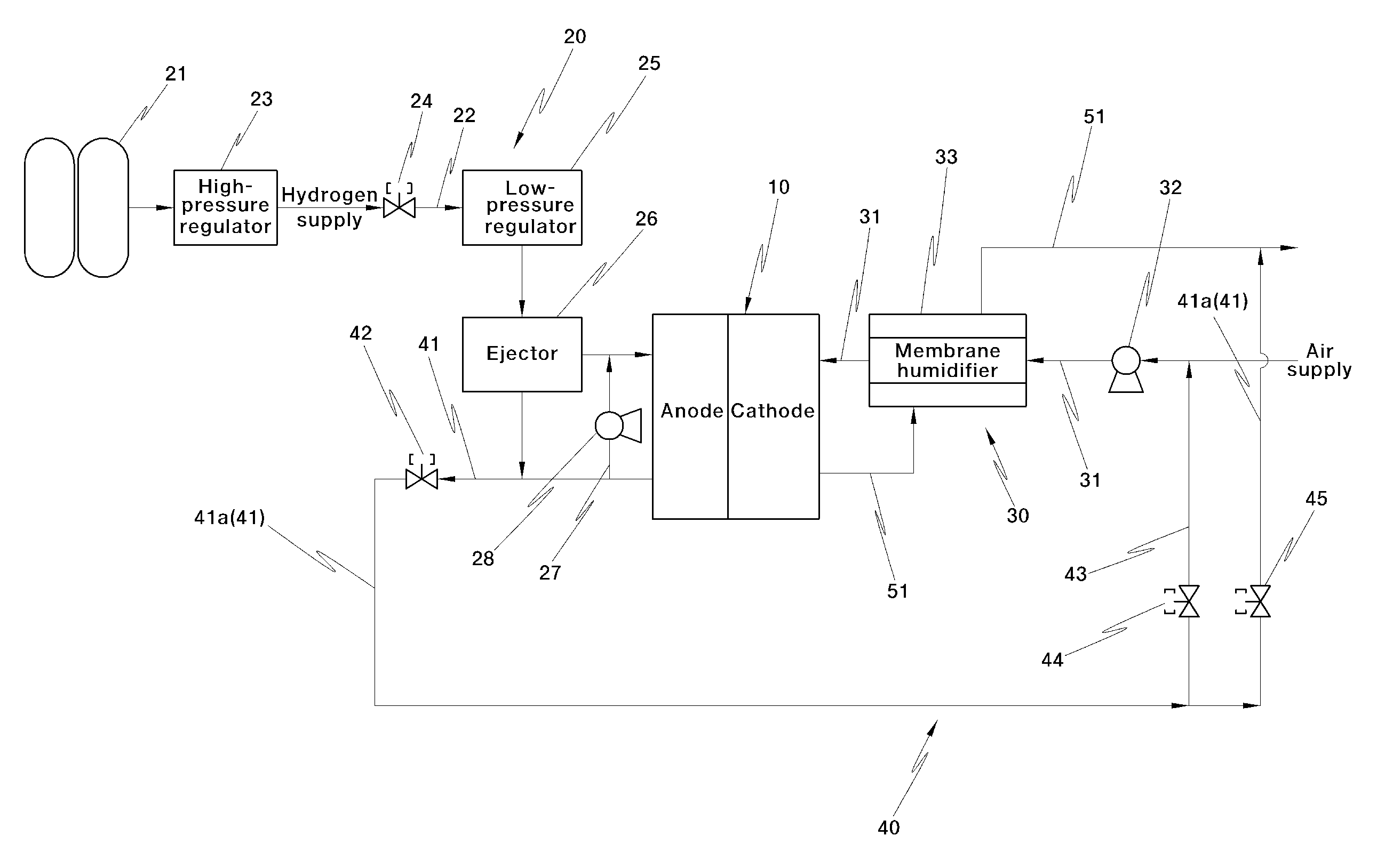
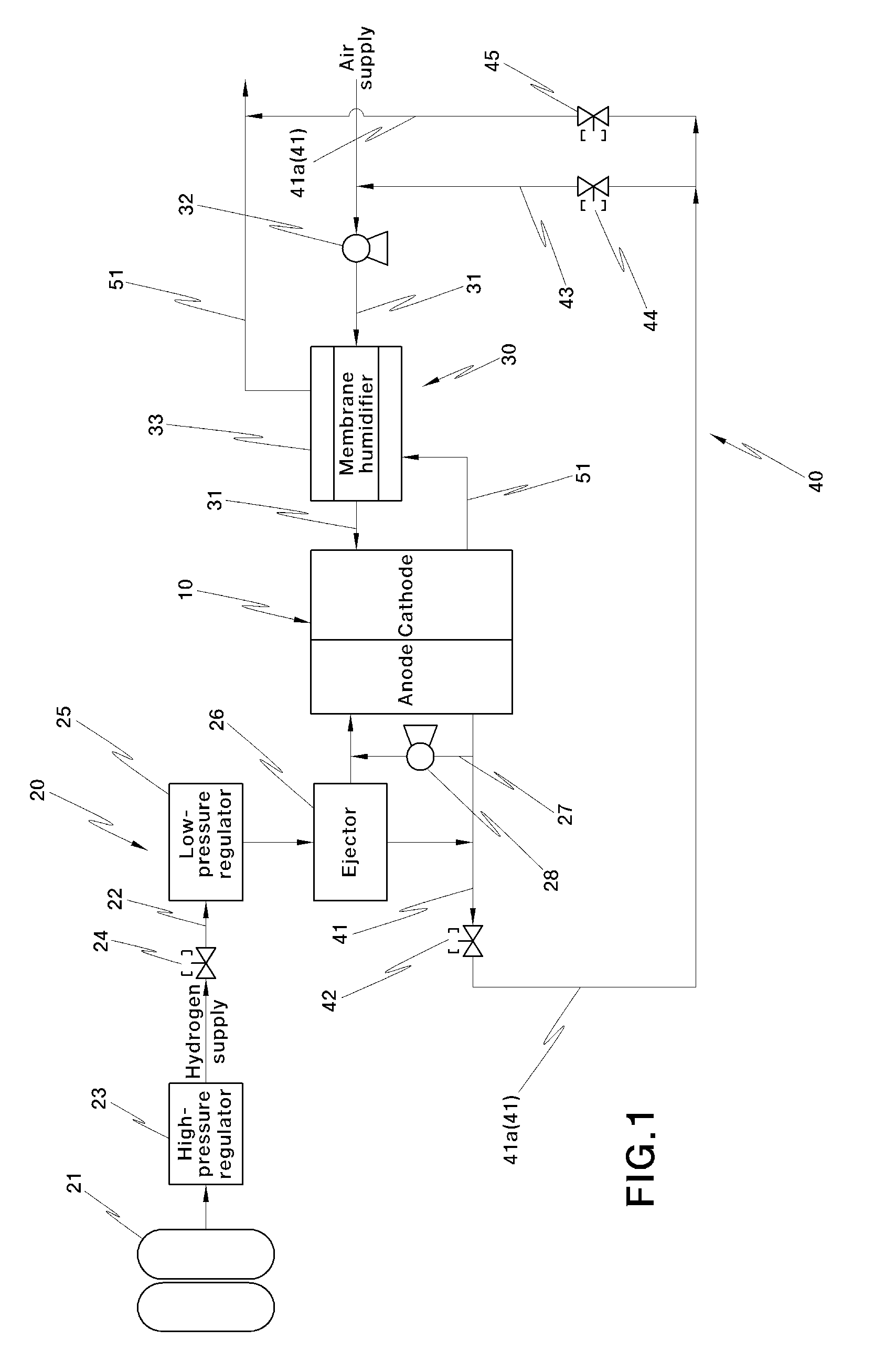
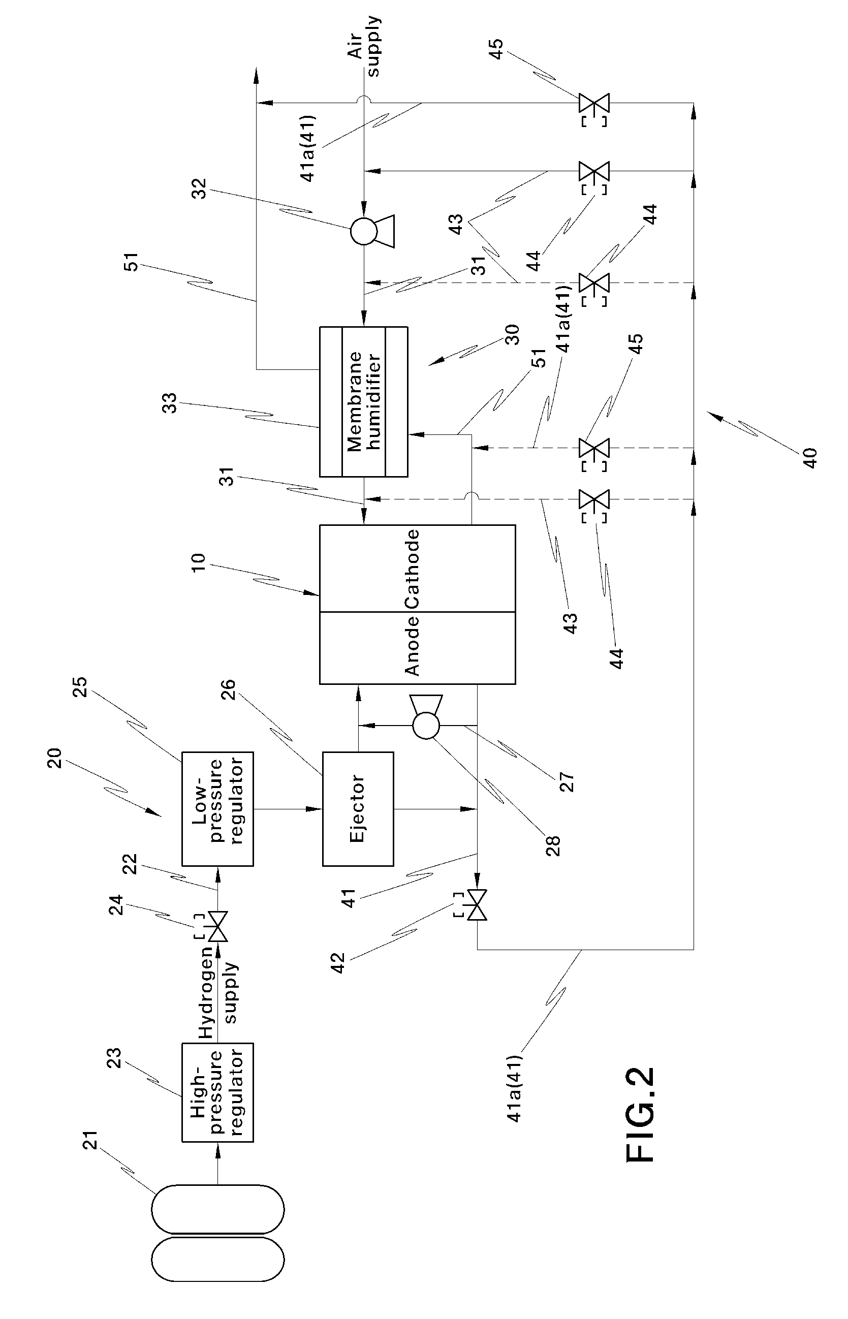
[0034]In a preferred aspect, the present invention features a hydrogen exhaust system for a fuel cell vehicle, comprising a hydrogen exhaust line, a hydrogen purge valve provided in the hydrogen exhaust line, an outlet line as a part of the hydrogen exhaust line at a rear end of the hydrogen purge valve, an inlet line branched from the outlet line, a vehicle state detector for detecting a vehicle state, a controller; and a valve means.

[0035]In one embodiment, the hydrogen exhaust line is provided at an anode outlet of a fuel cell stack.

[0036]In another embodiment, the outlet line exhausts purge hydrogen discharged by the hydrogen purge valve to an air exhaust line at a cathode outlet of the fuel cell stack.

[0037]In another further embodiment, the inlet line exhausts purge hydrogen to an air supply line at a cathode inlet of the fuel cell stack.

[0038]In still another further embodiment, the controller outputs a control signal for selecting either the cathode outlet or the cathode inl...


PUM

PropertyMeasurementUnit
speedaaaaaaaaaa
speed detectoraaaaaaaaaa
temperatureaaaaaaaaaa

Abstract

The present invention provides a hydrogen exhaust system for a fuel cell vehicle, which is configured to actively control an exhaust path of hydrogen discharged from an anode of a fuel cell stack to maximize the safety of the vehicle by minimizing the possibility of explosion due to hydrogen exhaust and ensure the silence of the vehicle by minimizing noise generated during hydrogen exhaust. Moreover, the present invention provides a hydrogen exhaust system for a fuel cell vehicle, which can improve the performance and power of the fuel cell stack by supplying water discharged from the fuel cell stack to an air supply line of the fuel cell stack together with purge hydrogen discharged to a hydrogen exhaust line to increase the humidification performance of the fuel cell stack.

Description

CROSS-REFERENCE TO RELATED APPLICATION[0001]This application claims under 35 U.S.C. §119(a) the benefit of Korean Patent Application No. 10-2009-0081178 filed Aug. 31, 2009, the entire contents of which are incorporated herein by reference.BACKGROUND[0002](a) Technical Field[0003]The present disclosure relates to a fuel cell system. More particularly, the present invention relates to a hydrogen exhaust system for a fuel cell vehicle, which exhausts hydrogen suitably discharged from an anode of a fuel cell stack.[0004](b) Background[0005]A fuel cell system applied to a hydrogen fuel cell vehicle as an environmental friendly vehicle preferably comprises a fuel cell stack for suitably generating electricity by an electrochemical reaction of reactant gases, a hydrogen supply system (“fuel processing system”) for suitably supplying hydrogen as a fuel to the fuel cell stack, an air supply system (“air processing system”) for suitably supplying oxygen-containing air as an oxidant required ...

Claims


Application Information

Patent Timeline
Patent Type & Authority Applications(United States)
IPC IPC(8): B60K13/04H01M8/04
CPCB60K13/04H01M8/04097H01M8/04149Y02E60/50H01M8/04231H01M8/04805H01M8/04179H01M8/04
Inventor KWON, BU KILLEE, HYUN JOONSHIM, HYO SUBJUNG, SE KWONPARK, YONG SUN
Owner HYUNDAI MOTOR CO LTD
Why Eureka
Try Eureka