Integrated RF electrodeless plasma lamp device and methods

a plasma lamp and electrodeless technology, applied in the field of lighting techniques, can solve the problems of high initial cost, high energy consumption of electrodeless lamps, and many limitations of electrodeless lamps, and achieve the effects of simple and cost-effective manufacture, improved manufacturability and design flexibility, and simple installation

Inactive Publication Date: 2011-03-03
TOPANGA USA
View PDF16 Cites 2 Cited by
  • Summary
  • Abstract
  • Description
  • Claims
  • Application Information

AI Technical Summary

Benefits of technology

[0011]Benefits are achieved over existing techniques using the present invention. In a specific embodiment, the present invention provides a method and device having configurations of input, output, and feedback coupling elements that provide for electromagnetic coupling to the bulb whose power transfer and frequency resonance characteristics in a suitable form factor. In a preferred embodiment, the present invention provides a method and configurations with an arrangement that provides for improved manufacturability as well as design flexibility. Other embodiments may include integrated assemblies of the output coupling element and bulb that function in a complementary manner with the present coupling element configurations and related methods for conventional lighting applications to replace the Edison socket or mogul socket. In a specific embodiment, the present method and resulting structure are relatively simple and cost effective to manufacture for commercial applications as well as simple to install into existing fixtures and sockets with minimal or no change to the existing fixtures. Depending upon the embodiment, one or more of these benefits may be achieved. These and other benefits may be described throughout the present specification and more particularly below.

Problems solved by technology

Although highly successful, the Edison bulb consumed much energy and was generally inefficient.
Fluorescent lighting is much more efficient than incandescent lighting, but often has a higher initial cost.
Although somewhat successful, the electrodeless lamp still had many limitations, including the inability of the lamp to fit into standard light sockets such as the Edison socket or mogul socket.

Method used


Image

  • Integrated RF electrodeless plasma lamp device and methods
  • Integrated RF electrodeless plasma lamp device and methods
  • Integrated RF electrodeless plasma lamp device and methods

Examples


Embodiment Construction

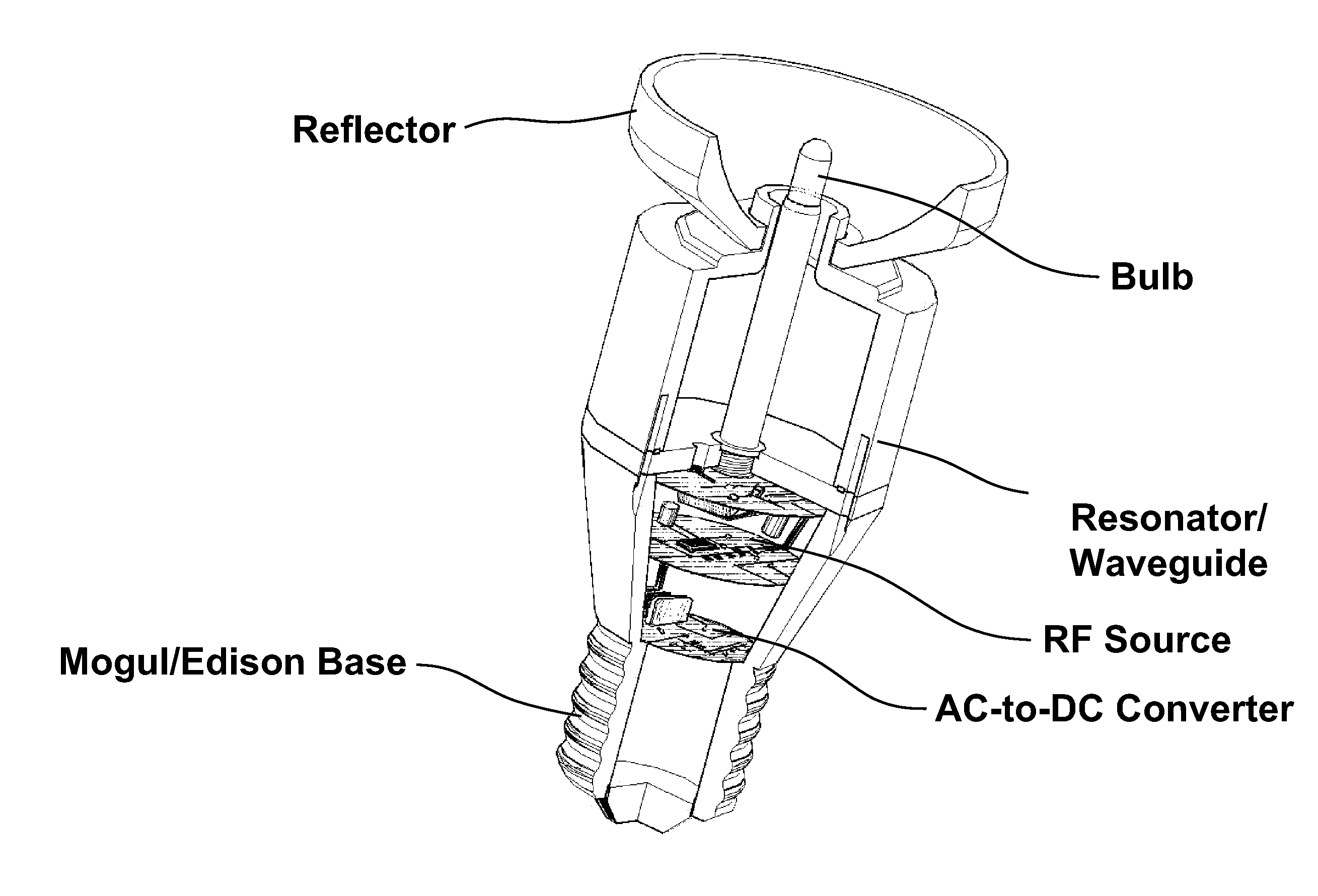
[0025]According to the present invention, techniques generally for lighting are provided. More particularly, the present invention provides a method and device using an electrodeless plasma lighting device having one of a plurality of base configurations. Merely by way of example, such configurations can include at least Edison base or mogul base, but can be others.

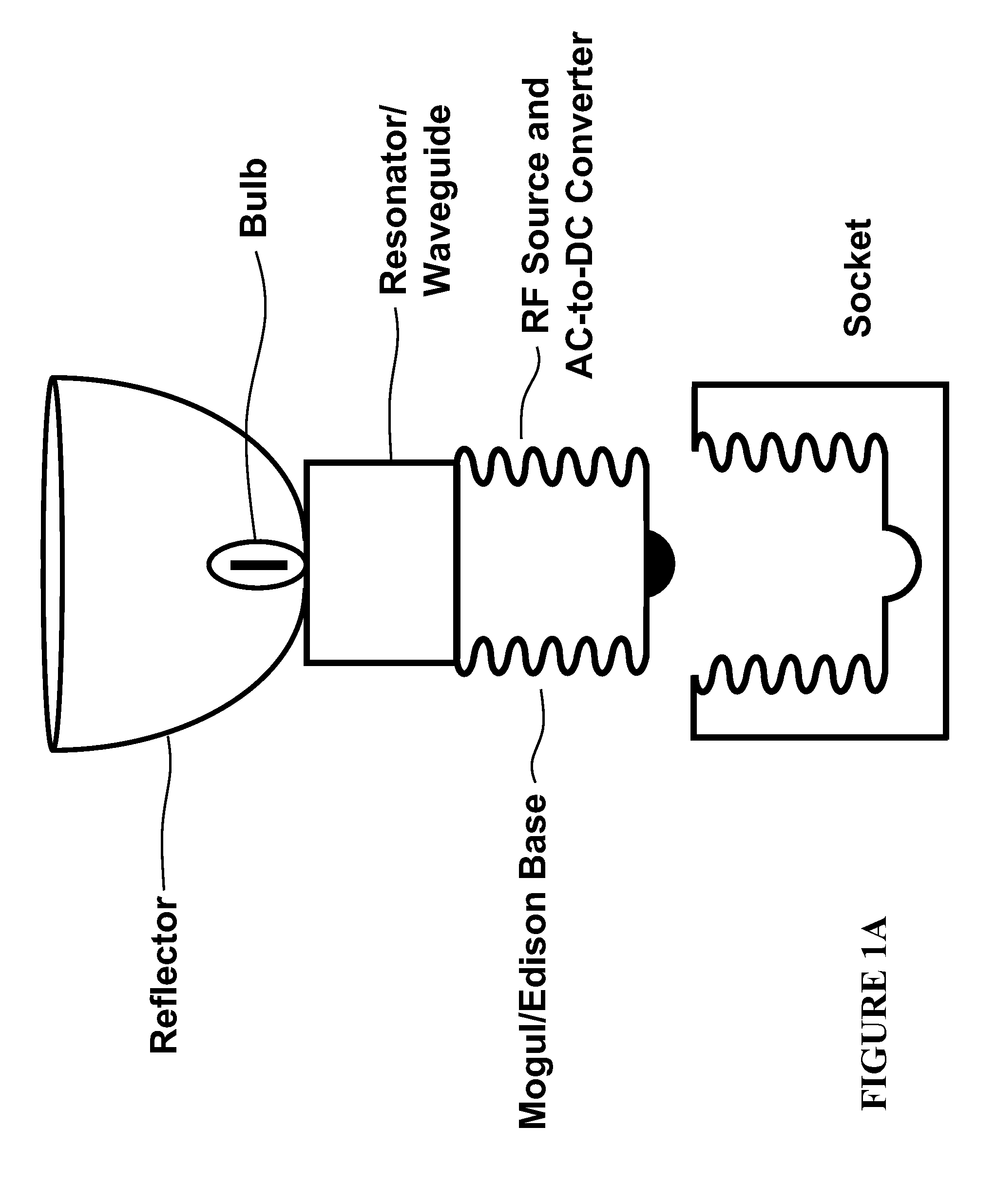
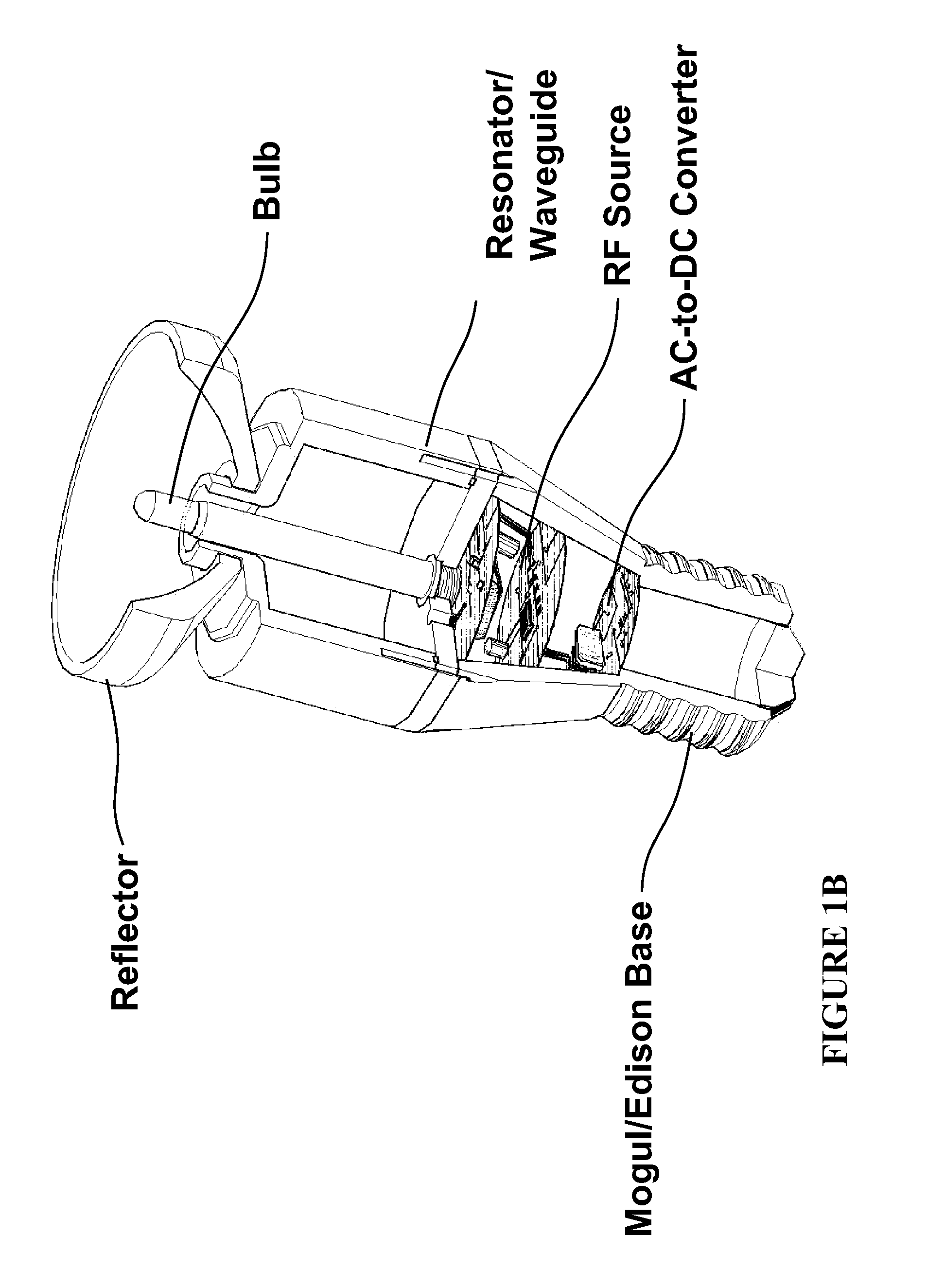
[0026]FIG. 1A is a simplified perspective view of an electrodeless plasma lamp integrated with a base. The base integrated lamp includes a base that is mechanically and integrally coupled with the below described various plasma lamp assemblies. The base member can be of any suitable size and shape to fit into a socket, including but not limited to an Edison base. More specifically, the base member can be but is not limited to an E14, E17, E26, E27, E39 and E40 or any other Edison type base or mogul type base. The base provides two electrical inputs to create an electrical circuit, and allow for the powering of the lamp ap...


PUM


Abstract

An RF electrode-less plasma lighting device. The device has a base member, which has an outer region capable of being coupled to first AC potential and an inner region capable of being coupled to a second AC potential. In a preferred embodiment, the device has an RF module mechanically and integrally coupled to the base member. The RF module has an RF source, which has an output. The RF module has a first DC input and a second DC input. The first DC input of the RF module is coupled to the first DC potential and the second DC input of the RF module is coupled to the second DC potential. In a specific embodiment, the present device has an RF electrodeless plasma lighting assembly integrally coupled to the base member. The RF plasma lighting assembly has an RF input, which is coupled to the output of the RF source.

Description

CROSS-REFERENCES TO RELATED APPLICATIONS[0001]This application claims priority to U.S. Provisional Patent Application No. 61 / 239,056, filed Sep. 1, 2009, entitled “INTEGRATED RF ELECTRODELESS PLASMA LAMP DEVICE AND METHODS” which is commonly owned and incorporated by reference in its entirety herein for all purposes.BACKGROUND OF THE INVENTION[0002]The present invention relates generally to lighting techniques. More particularly, the present invention provides a method and device using an electrodeless plasma lighting device having one of a plurality of base configurations. Merely by way of example, such configurations can include at least an Edison base or a mogul base, but can be others.[0003]From the early days, human beings have used a variety of techniques for lighting. Early humans relied on fire to light caves during hours of darkness. Fire often consumed wood for fuel. Wood fuel was soon replaced by candles, which were derived from oils and fats. Candles were then replaced, ...

Claims


Application Information

Patent Timeline
Patent Type & Authority Applications(United States)
IPC IPC(8): H01J7/44
CPCH01J65/044H01J61/56
Inventor MATLOUBIAN, MEHRANESPIAU, FREDERICK M.
Owner TOPANGA USA
Why Eureka
Try Eureka