Buck converter for making power available to at least one LED

a technology of buck converter and led, which is applied in the direction of electric variable regulation, process and machine control, instruments, etc., can solve the problems of high cost, high cost, and often exceed the budget provided for mass-produced products, so as to reduce ripple on current and no loss

Inactive Publication Date: 2011-03-03
OSRAM GMBH
View PDF7 Cites 10 Cited by
  • Summary
  • Abstract
  • Description
  • Claims
  • Application Information

AI Technical Summary

Benefits of technology

[0003]The object of the present invention is therefore to develop a Buck converter of the type mentioned initially such that it can be produced at extremely low cost.
[0007]These measures make it possible to provide an extremely simple and low-cost Buck converter design. They furthermore allow operation in the critical conduction mode, in which essentially only switching-off losses occur for the Buck main switch.
[0009]Preferably, the Buck converter furthermore includes a timing element which is coupled between the current measurement resistor and the control electrode of the first auxiliary switch. This makes it possible to ensure that the first auxiliary switch remains switched off even though the current produced at its control electrode is already falling because of the Buck main switch having been switched off. By way of example, a preferred time constant is in the order of magnitude between 0.2 and 10 μs, preferably 11 μs.
[0014]Preferably, the Buck converter furthermore includes a second auxiliary winding, which is coupled to the Buck inductor and has a first connection which is coupled to the first input connection and a second connection which is coupled to the control electrode of the second auxiliary switch. In this case, preferably, a non-reactive resistor, preferably a non-reactive resistor connected in series with a diode, is coupled between the second connection of the second auxiliary winding and the control electrode of the second auxiliary switch. In this case, in particular, the second auxiliary winding is coupled to the Buck inductor such that, during the phase in which the Buck main switch is switched off, or the demagnetization phase of the Buck inductor, a current is provided to the control electrode of the second auxiliary switch such that the second auxiliary switch is switched off. This makes it possible to prevent any current flowing through the non-reactive resistor which couples the working electrode of the second auxiliary switch to the working electrode of the first auxiliary switch, as a result of which a power loss occurs in this non-reactive resistor only in the brief phases in which the Buck main switch is switched on, and this resistor is operated with virtually no losses during the long phases in which the Buck main switch is switched off.

Problems solved by technology

These embodiments have the disadvantage that they all require quite considerable complexity and the use of expensive components.
By way of example, the switch in a flyback converter for the European mains voltage must have a withstand voltage of at least 700 V. The costs that this results in frequently exceed the budget provided for use in mass-produced products.

Method used


Image

  • Buck converter for making power available to at least one LED
  • Buck converter for making power available to at least one LED
  • Buck converter for making power available to at least one LED

Examples


Embodiment Construction

[0003]The object of the present invention is therefore to develop a Buck converter of the type mentioned initially such that it can be produced at extremely low cost.

[0004]This object is achieved by a Buck converter having the features of patent claim 1.

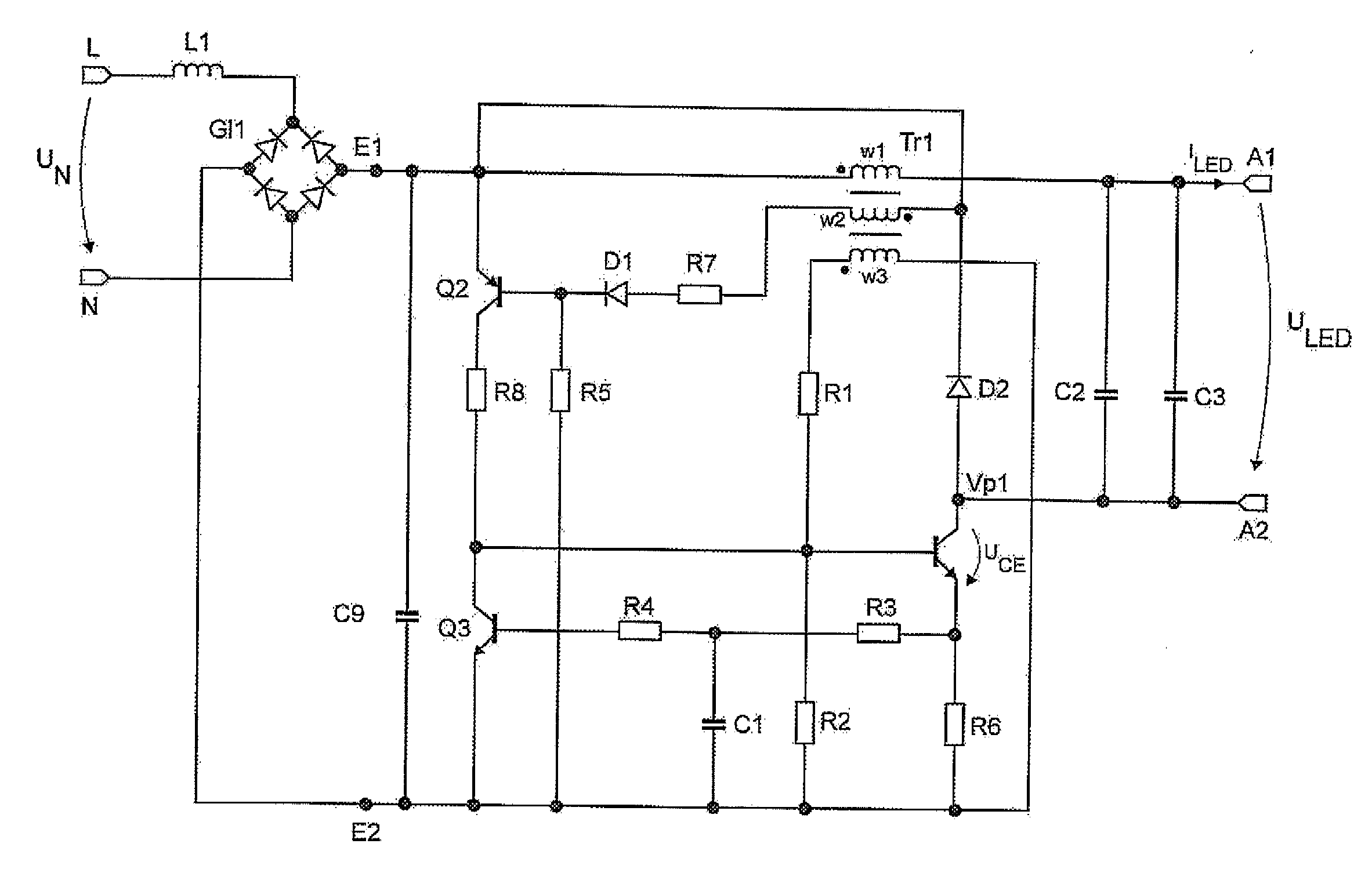
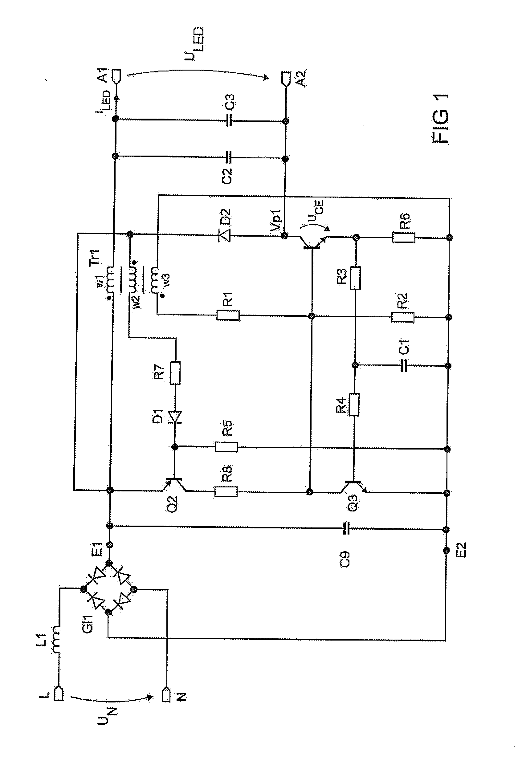
[0005]The present invention is based on the discovery that very low-cost bipolar transistors can be used, for example as represented by the MPSA42 type known from the video field, in which currents required for a power LED on the one hand still have only a low current gain but on the other hand have to be switched off at a defined time, in order that a defined current is likewise produced for the LED.

[0006]The invention is now furthermore based on the load on the switch being reduced by coupling the Buck diode and the Buck main switch in series between the first and the second input connection, wherein the connecting point between the Buck diode and the Buck main switch is coupled to the second output connection. The first connection...


PUM


Abstract

A buck converter for providing a current for an LED includes an input for connection of a DC voltage source; an output for connection of the LED; and a Buck diode, a Buck inductor and a Buck main switch which has a control electrode, a working electrode and a reference electrode. The diode and the main switch are coupled in series, wherein the connecting point between the diode and the main switch is coupled to the second output connection. The converter includes: an auxiliary winding which is coupled to the inductor and has a connection which is coupled to the second input connection and a connection which is coupled to the control electrode of the switch, wherein the auxiliary winding is coupled to the inductor such that, when current is flowing through the switch, a current is provided through the auxiliary winding to the control electrode of the switch.

Description

TECHNICAL FIELD[0001]The present invention relates to a Buck converter for providing a current for at least one LED having an input having a first and a second input connection for connection of a DC voltage source, an output having a first and a second output connection for the connection of the at least one LED, and a Buck diode, a Buck inductor and a Buck main switch, which has a control electrode, a working electrode and a reference electrode.PRIOR ART[0002]As LEDs are being introduced into wide areas of general lighting, there is a major requirement for simple and low-cost power supply circuits for these components. One converter circuit which is known for operation of LEDs for mains applications is the so-called flyback converter. Furthermore, there are now a multiplicity of in particular integrated circuits for Buck or boost converters, for example the MXHV9910 control IC from the company Micronix. These embodiments have the disadvantage that they all require quite considerab...

Claims


Application Information

Patent Timeline
Patent Type & Authority Applications(United States)
IPC IPC(8): H05B41/36H05B44/00
CPCH02M3/1563H05B33/0815Y02B20/346H05B33/0818H05B45/375Y02B20/30H02M3/155
Inventor RUDOLPH, BERND
Owner OSRAM GMBH
Why Eureka
Try Eureka