

Inductor and DC-DC converter
- Summary
- Abstract
- Description
- Claims
- Application Information
AI Technical Summary
Benefits of technology
Problems solved by technology
Method used
Image

Examples
Embodiment Construction
[0057]An inductor according to a first preferred embodiment of the present invention is described with reference to the drawings.
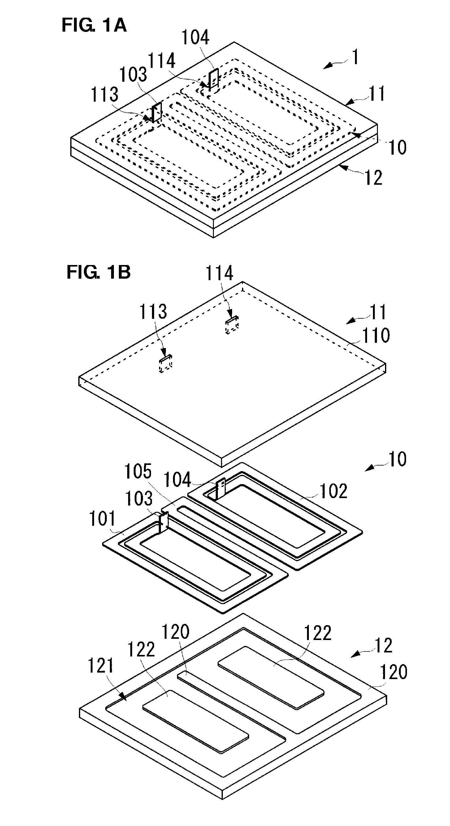
[0058]FIG. 1A is an external perspective view of an inductor 1 according to the present preferred embodiment, and FIG. 1B is an exploded perspective view of the inductor 1.
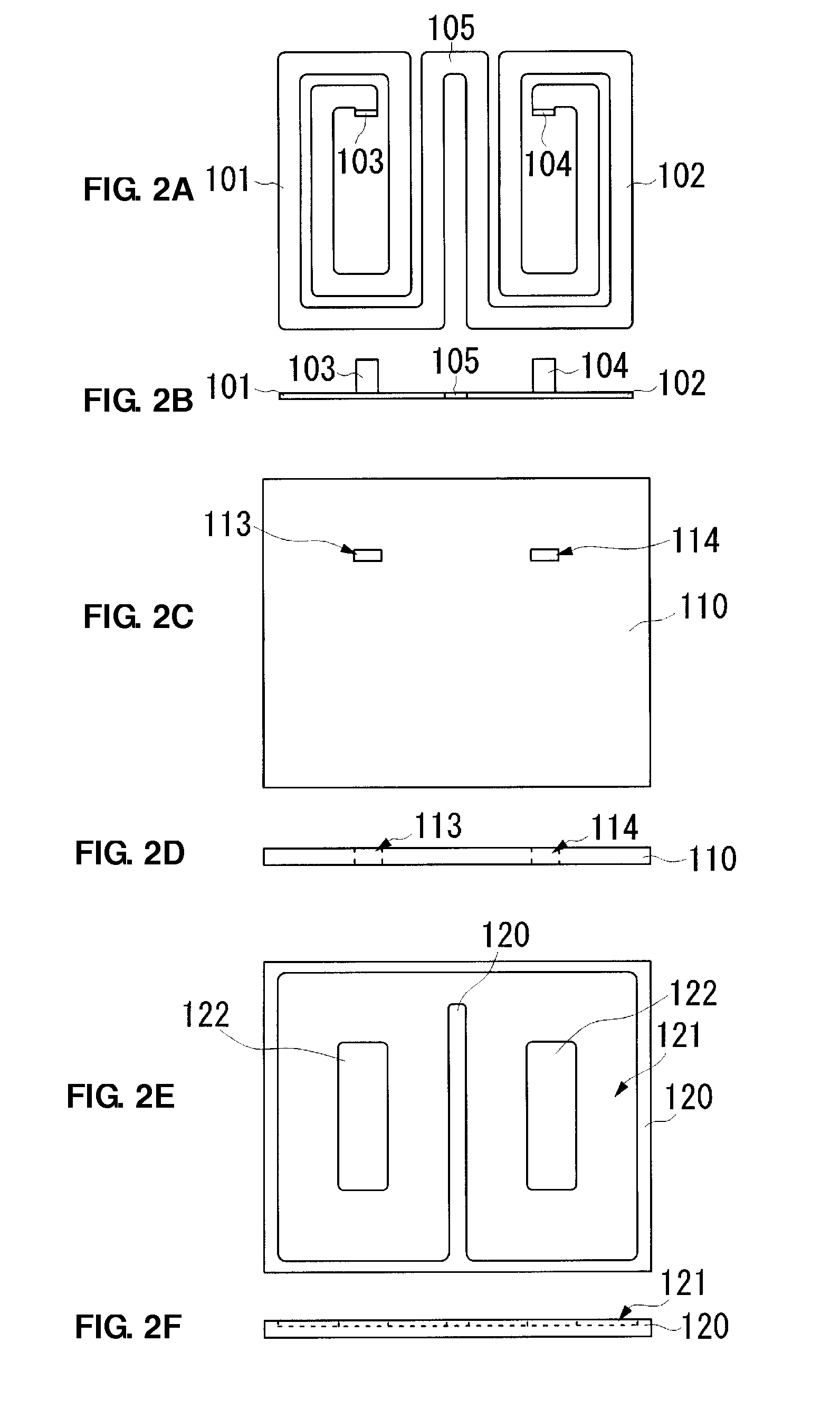
[0059]FIG. 2A is a plan view of a coil electrode section 10, and FIG. 2B is a side view of the coil electrode section 10. FIG. 2C is a plan view of a first magnetic layer 11, and FIG. 2D is a side view of the first magnetic layer 11. FIG. 2E is a plan view of a second magnetic layer 12, and FIG. 2F is a side view of the second magnetic layer 12.
[0060]FIG. 3 is a side cross-sectional view that schematically illustrates behavior of magnetic fields produced from the inductor 1 according to the present preferred embodiment of the present invention. In FIG. 3, the thick chain double-dashed lines schematically indicate a portion of magnetic fields occurring in the inductor 1.
[0061]As illustrat...
PUM
 Abstract
Description
Claims
Application Information