Optical disk device

a technology of optical disk and optical disk, applied in the direction of digital signal error detection/correction, instruments, recording signal processing, etc., can solve the problem of large number of errors, and achieve the effect of reducing the occurrence of errors

Active Publication Date: 2011-03-03
RENESAS ELECTRONICS CORP
View PDF2 Cites 24 Cited by
  • Summary
  • Abstract
  • Description
  • Claims
  • Application Information

AI Technical Summary

Benefits of technology

[0020]According to the technique of the present invention, it is possible to reduce the occurrence of e...

Problems solved by technology

This may cause a ...

Method used


Image

  • Optical disk device
  • Optical disk device
  • Optical disk device

Examples


first exemplary embodiment

[0073]FIG. 11 shows an optical disk device 100 according to a first exemplary embodiment of the present invention. The optical disk device 100 is compliant with DVD-R / RW standards, and records and reproduces reproduction information on and from a DVD-R / RW optical disk. The optical disk device 100 includes an optical head 104, a recording unit 110, and a reproduction unit 120.

[0074]The recording unit 110 records synchronization information and reproduction information on an optical disk 102. The recording unit 110 includes a wobble signal generation unit 112, an LPP detection unit 114, a recording clock generation circuit 115, an encoder 116, and a laser control unit 117. The wobble signal generation unit 112 generates a wobble signal WS by performing filtering processing for removing noise from a differential signal of reflected laser light which is irradiated onto the optical disk 102 by the optical head 104. The LPP detection unit 114 performs LPP detection on the wobble signal WS...

second exemplary embodiment

[0117]A second exemplary embodiment of the present invention also relates to an optical disk device compliant with the DVD-R / RW standards. The optical disk device of the second exemplary embodiment is equivalent to the optical disk device 100 of the first exemplary embodiment shown in FIG. 11 except that the correction unit 140 is replaced by a correction unit 200 shown in FIG. 15. In the second exemplary embodiment, only the correction unit 200 will be described. Components in FIG. 15 that are identical to those of the correction unit 140 shown in FIG. 12 are denoted by the same reference numerals, and the detailed description thereof is omitted.

[0118]The correction unit 200 performs correction processing for eliminating the effect of the LPP on the RF signal, specifically, the equalized digital RF signal P5 in this exemplary embodiment. The correction unit 200 includes two FIFOs (212 and 214), a subtractor 230, a first averaging unit 231, the correction execution unit 180, and a c...


PUM


Abstract

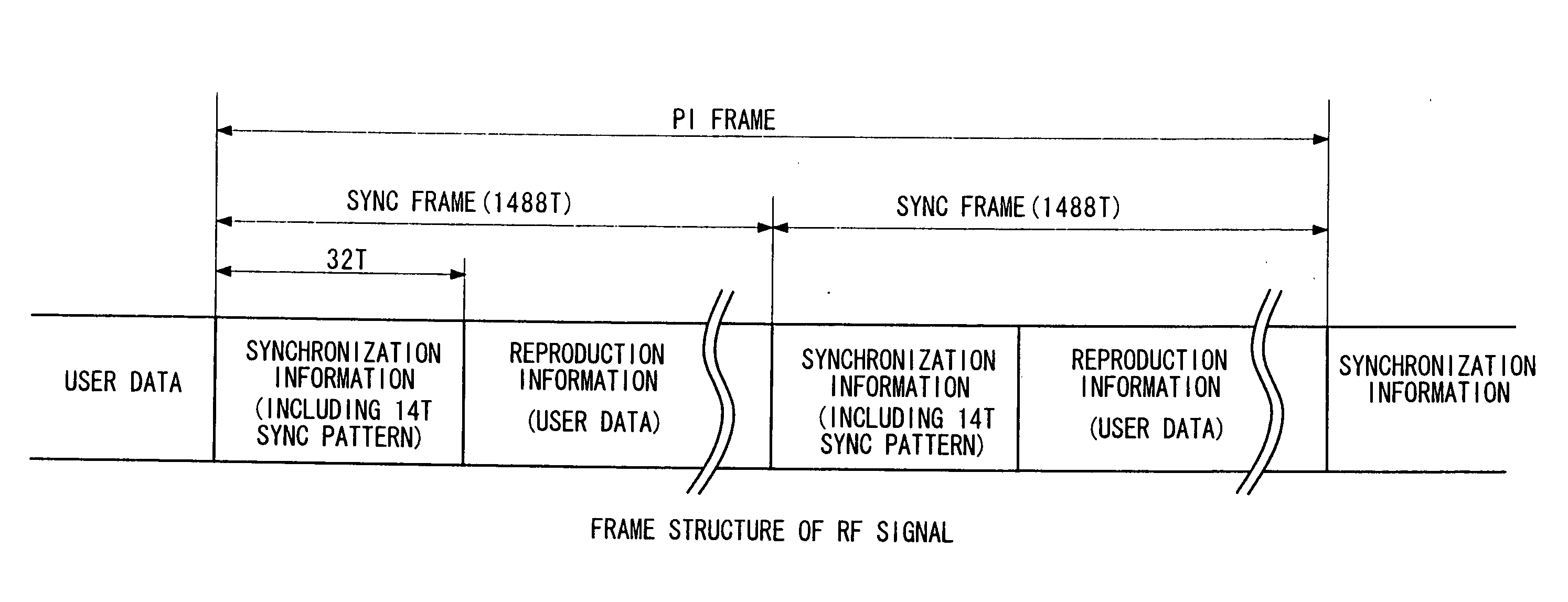
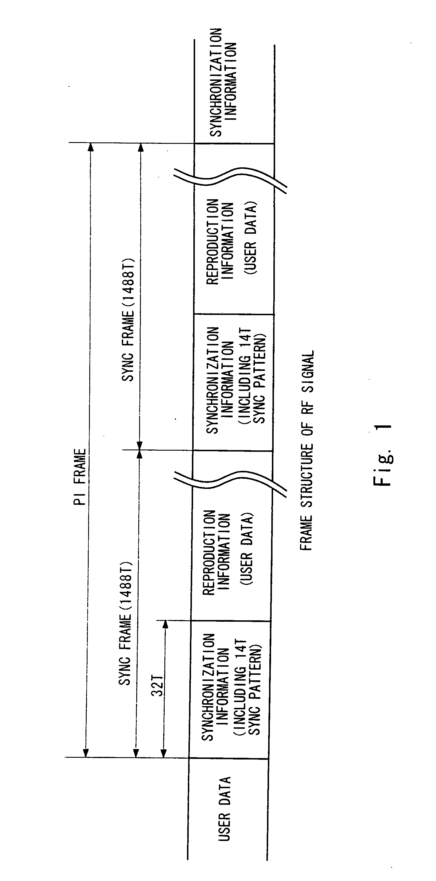
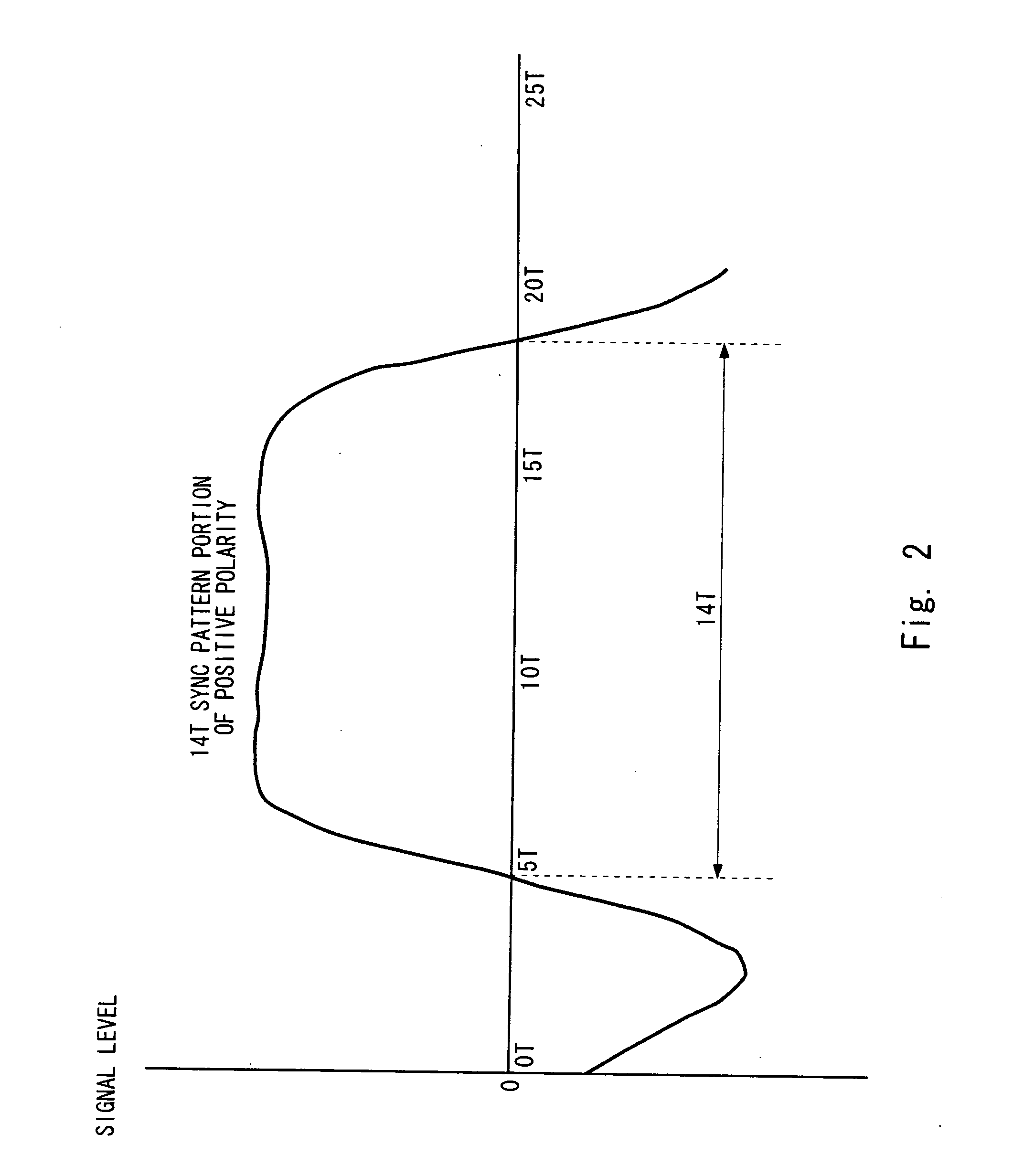
An LPP detection unit detects an LPP from a wobble signal. A correction unit obtains a difference set by performing processing of calculating a difference in signal level between an LPP-present sync pattern portion and a non-LPP sync pattern portion having the same polarity, and executes correction on an RF signal at a timing when the LPP is detected, by using the difference set. The LPP-present sync pattern portion is a sync pattern portion obtained when the LPP is detected at the timing of the sync pattern portion positioned at the head of a sync frame of the RF signal. The non-LPP sync pattern portion is a sync pattern portion obtained when no LPP is detected at the timing of the sync pattern portion of the sync frame. In the case of reproducing information recorded on a DVD-R/RW optical disk, the occurrence of errors due to the effect of the LPP can be reduced.

Description

INCORPORATION BY REFERENCE[0001]This application is based upon and claims the benefit of priority from Japanese patent application No. 2009-198525, filed on Aug. 28, 2009,the disclosure of which is incorporated herein in its entirety by reference.BACKGROUND[0002]1. Field of the Invention[0003]The present invention relates to an optical disk device, and more particularly, to a technique for reproducing information recorded on an optical disk compliant with DVD-R and DVD-RW standards.[0004]2. Description of Related Art[0005]FIG. 16 shows a partial plan view of an optical disk compliant with DVD-R and DVD-RW (hereinafter, collectively referred to as “DVD-R / RW”) standards. Referring to FIG. 16, the optical disk has a groove area in which user information is recorded, and an area between adjacent grooves is called a land. Although the grooves are meandering, the grooves and lands are each shown in a rectangular shape for convenience of illustration.[0006]Each land has auxiliary informati...

Claims


Application Information

Patent Timeline
IPC IPC(8): G11B20/10G11B27/36
CPCG11B20/10046G11B20/10212G11B2220/2537G11B20/10425G11B2020/1287G11B20/10333
Inventor ASHIZAWA, TETSUOHONMA, HIROMI
Owner RENESAS ELECTRONICS CORP
Why Eureka
Try Eureka