
Radiation therapy skin marker

Inactive Publication Date: 2011-03-03
IZI MEDICAL PROD
View PDF17 Cites 22 Cited by
  • Summary
  • Abstract
  • Description
  • Claims
  • Application Information

AI Technical Summary

Benefits of technology

[0010]In order to overcome shortcomings of techniques used to depict portal fields, a specially designed device is presented. This device is easy to apply to the skin of a patient. The device is reliable in that it may retain its original position from about seven and to about ten days. Yet, it may be repositioned easily without risk to patient or personnel. Furthermore, it is removable without leaving any permanent traces on the patient's skin.

Problems solved by technology

However, there are several disadvantages to tattooing, even though it may seem to be the most optimal means to establish portal boundaries.
One problem is that tattoos are difficult to recognize on dark skin.
Thus, tattoos too may not be completely visible during the radiation therapy treatment.
An additional problem is that the tattooing process punctures the patient's skin multiple times and, therefore, has the potential to expose radiation therapy personnel to the patient's blood and the patient's blood to out-side contaminants.
This exposure creates a risk that the radiation therapy personnel or the patient may be contaminated with various infectious organisms transmitted by blood exposure.
Two further problems are associated with the permanency of tattoos.
First, a radiation therapy portal boundary tattoo is aesthetically unattractive.
This is especially problematic when the tattoo is placed on skin surfaces which are not ordinarily covered by clothing.

Method used


Image

  • Radiation therapy skin marker
  • Radiation therapy skin marker
  • Radiation therapy skin marker

Examples


Embodiment Construction

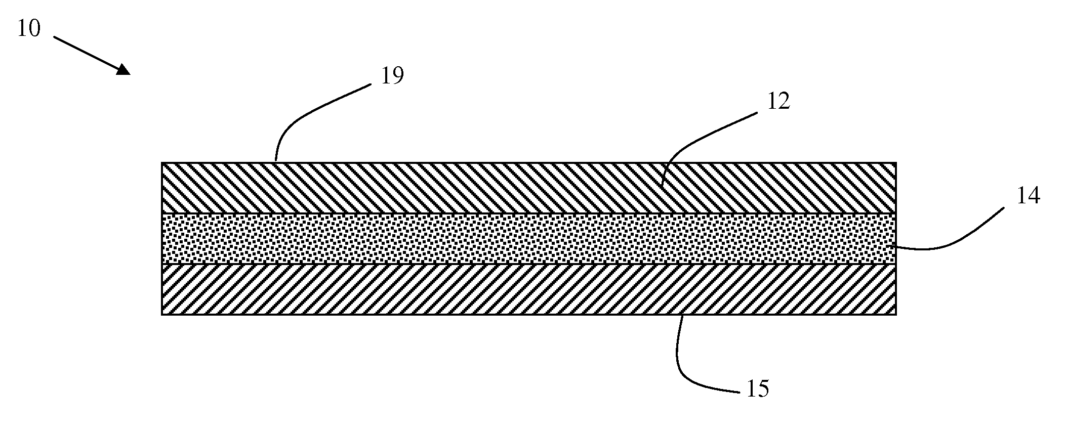
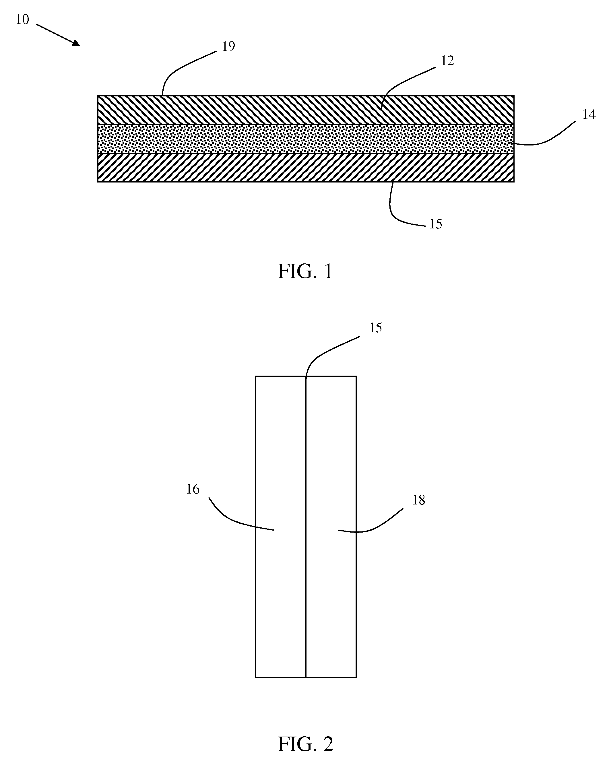
[0020]An embodiment of the invention relates to radiation therapy skin markers to delineate radiation therapy portal areas of a patient to be treated with radiation. As seen in FIGS. 1 and 2, a radiation therapy skin marker 10 comprises a substrate 12 having a first surface 19 and a second surface (not shown). Surface 19 of substrate 12 is lined with an ink to facilitate the outlining of the treatment field. The second surface is coated with an adhesive layer 14 which is protected by release liner 15, optionally divided into multiple segments, shown here as 16 and 18.

[0021]Substrate 12 of radiation therapy skin marker 10 is prepared from material that is both conformable to the contours of the body, and flexible so as to permit free movement of the body part wearing the product. Further, substrate 12 is lightweight, and is elastic in character. In an embodiment of the invention, substrate 12 is a non-woven substrate, such as a film having a thickness in the range from about 1 mil to...


PUM


Abstract

Radiation therapy skin markers used to delineate radiation therapy portal areas of a patient to be treated with radiation are described. The radiation therapy skin marker includes comprises a substrate having a first surface and a second surface. The first surface of the substrate is lined with an ink to facilitate the outlining of the treatment field. The second surface is coated with an adhesive layer which is protected by release liner.

Description

[0001]The invention relates to devices used to delineate radiation therapy portal areas of patients to be treated with radiation. More particularly, the invention relates to markers used to delineate radiation therapy portal areas of patients to be treated with radiation. Even more particularly, the invention relates to a lined markers used to delineate radiation therapy portal areas of patients to be treated with radiation.BACKGROUND OF THE INVENTION[0002]Radiation therapy is a common method in the treatment of those individuals diagnosed with cancer. Radiation therapy is used to treat cancer patients in two ways: for curative purposes and for palliative reasons.[0003]Virtually all radiation therapy centers are equipped with simulators, which includes a fluoroscopic imaging unit equipped with all the characteristics and parameters found on the radiation treatment units. With the help of diagnostic imaging such as computerized x-ray tomography (CT) and magnetic resonance imaging (MR...

Claims


Application Information

Patent Timeline
IPC IPC(8): A61N5/10A61B6/08
CPCA61B19/54A61B2017/00902A61B2017/00951A61N5/1049A61B2019/5441A61B2019/545A61B2019/5491A61B2019/5437A61B2090/3991A61B90/39A61B2090/3937A61B2090/3941A61B2090/395
Inventor SHAFER, HELEN ZINREICH
Owner IZI MEDICAL PROD
Learn More