Exposure method, exposure apparatus, and device manufacturing method

Active Publication Date: 2011-03-03
NIKON CORP
View PDF4 Cites 25 Cited by
  • Summary
  • Abstract
  • Description
  • Claims
  • Application Information

AI Technical Summary

Benefits of technology

[0023]According to this method, it becomes possible to drive the movable body with good precision within the first movement area using the positional information of the movable body obtained using a plurality of heads corresponding to each of a plural

Problems solved by technology

Therefore, a scale with a large area becomes necessary; however, to make a highly precise scale having a large area is very difficult, as well as costly.
Accordingly, while it is desirable for

Method used


Image

  • Exposure method, exposure apparatus, and device manufacturing method
  • Exposure method, exposure apparatus, and device manufacturing method
  • Exposure method, exposure apparatus, and device manufacturing method

Examples


Embodiment Construction

[0037]An embodiment of the present invention will be described below, with reference to FIGS. 1 to 10B.

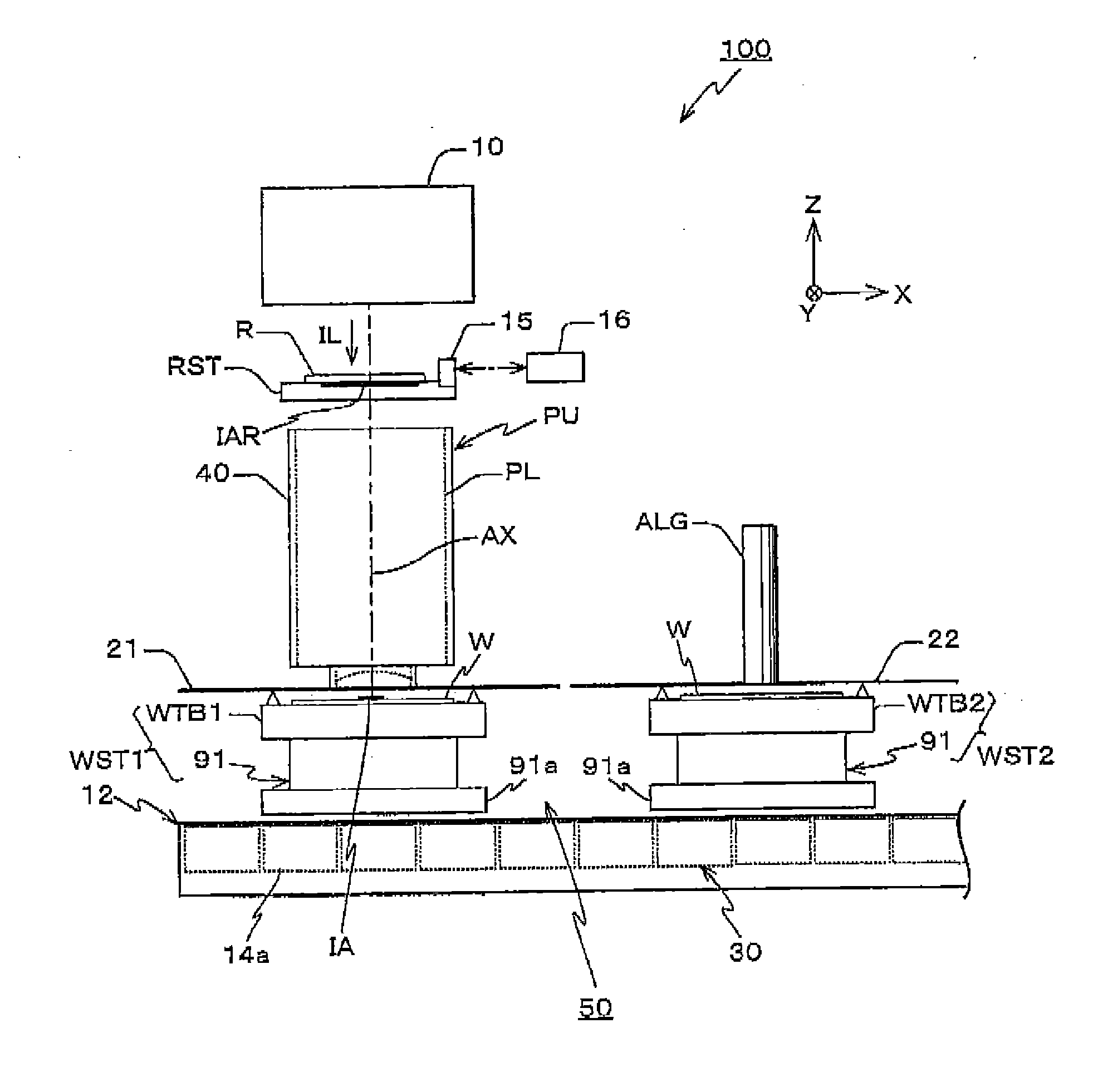
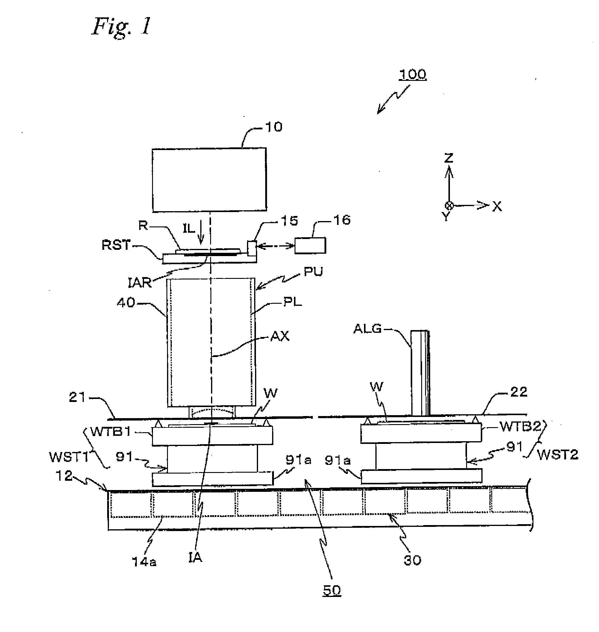
[0038]FIG. 1 schematically shows the configuration of an exposure apparatus 100 related to the present embodiment. Exposure apparatus 100 is a projection exposure apparatus of the step-and-scan method, namely the so-called scanner. As it will be described later, a projection optical system PL is arranged in the embodiment, and in the description below, a direction parallel to an optical axis AX of projection optical system PL will be described as the Z-axis direction, a direction within a plane orthogonal to the Z-axis direction in which a reticle and a wafer are relatively scanned will be described as the Y-axis direction, a direction orthogonal to the Z-axis and the Y-axis will be described as the X-axis direction, and rotational (inclination) directions around the X-axis, the Y-axis, and the Z-axis will be described as θ x, θ y, and θ z directions, respectively.

[0039]Exposure ap...


PUM

PropertyMeasurementUnit
Digital informationaaaaaaaaaa
Timeaaaaaaaaaa
Angleaaaaaaaaaa

Abstract

Within area where of four heads installed on a wafer stage, heads included in the first head group and the second head group to which three heads each belong that include one head different from each other face the corresponding areas on a scale plate, the wafer stage is driven based on positional information which is obtained using the first head group, as well as obtain the displacement (displacement of position, rotation, and scaling) between the first and second reference coordinate systems corresponding to the first and second head groups using the positional information obtained using the first and second head groups. By using the results and correcting measurement results obtained using the second head group, the displacement between the first and second reference coordinate systems is calibrated, which allows the measurement errors that come with the displacement between areas on scale plates where each of the four heads face.

Description

CROSS-REFERENCE TO RELATED APPLICATIONS[0001]This non-provisional application claims the benefit of Provisional Application No. 61 / 236,704 filed Aug. 25, 2009, the disclosure of which is hereby incorporated herein by reference in its entirety.BACKGROUND OF THE INVENTION[0002]1. Field of the Invention[0003]The present invention relates to exposure methods, exposure apparatuses, and device manufacturing methods, and more particularly to an exposure method and an exposure apparatus used in a lithography process to manufacture microdevices (electronic devices) such as a semiconductor device, and a device manufacturing method using the exposure method or the exposure apparatus.[0004]2. Description of the Background Art[0005]Conventionally, in a lithography process for manufacturing electron devices (microdevices) such as semiconductor devices (such as integrated circuits) and liquid crystal display devices, exposure apparatuses such as a projection exposure apparatus by a step-and-repeat...

Claims


Application Information

Patent Timeline
IPC IPC(8): G03F7/20G03B27/58
CPCG03F7/70725G03F7/70775G01B11/27Y10T29/49002G03F9/70G03F7/70358G03F7/70133H01L21/681G03F7/70516G03F7/20H01L21/027H01L21/0274G03F7/70483G06F7/20
Inventor SHIBAZAKI, YUICHI
Owner NIKON CORP
Why Eureka
Try Eureka