Human body implant structure, method of assembling the structure and method of disassembling the structure

a human body and implant technology, applied in the field of human body implant structure, can solve the problems of increasing the physical burden on patients, difficult to repair or inspect the dental implant structure, and difficult to remove the dental crown, so as to ensure the safe assembly of the safe artificial tooth base, easy mounting and removal, and the effect of preventing the slackening of the joining between the fixture and the abutmen

Active Publication Date: 2011-03-03
ARTHRO
View PDF30 Cites 29 Cited by
  • Summary
  • Abstract
  • Description
  • Claims
  • Application Information

AI Technical Summary

Benefits of technology

[0046]In step xii), the removed artificial tooth base is fitted onto the abutment which is mounted in the inside of the oral cavity of a patient by way of the taper fitting structure and, subsequently, the peripheral surface of the abutment is fitted into the fitting hole formed in the artificial tooth base in a close contact manner by threadedly engaging the artificial tooth base fastening screw jig which is separately prepared in the female threaded hole while bringing the distal end of the screw jig into contact with the upper end surface of the male screw rod below the screw jig. Accordingly, it is possible to assemble the safe artificial tooth base surely and easily without using an adhesive agent such as cement.
[0047]In step xiii), by closing the female threaded hole formed in a center portion of the artificial tooth base, the intrusion of a foreign material into the female threaded hole can be prevented. Further, slackening of the joining between the fixture and the abutment can be prevented.
[0048]In this manner, by constituting the dental implant structure using the respective steps having the constitution (4) as described above, the artificial tooth base and the abutment can be easily mounted and removed so that even a novice who is not an expert in implant assembling can surely perform the implant assembling operation and, at the same time, a medical psychological burden imposed on a patient can be reduced as much as possible.
[0049]According to the invention having the constitution (6), the upper male screw which is threadedly engaged with the female threaded hole vertically formed in the artificial tooth base is threadedly disengaged from an upper-end opening portion of the female threaded hole and is removed and, thereafter, a separation male screw jig which is constituted of a male screw and is prepared separately is threadedly engaged with the female threaded hole from which the male screw is removed until a lower end surface of the separation male screw jig is brought into pressure contact with a stepped portion positioned at a lowermost end of the female threaded hole and, thereafter, the separation male screw jig is further threadedly engaged with the female threaded hole so as to separate and remove the artificial tooth base from the abutment by making use of a reaction force of the artificial tooth base against the abutment. Accordingly, the artificial tooth base can be easily removed from the abutment and hence, the repair of the implant can be easily performed thus making the method of disassembling the human body implant structure advantageous also from viewpoints of operability and cost.
[0050]According to the invention having the constitution (9), the fixture and the abutment are formed into the integral structure and hence, the present invention can provide the implant structure which has the simple and reliable structure, the assembling method which can easily assemble the implant structure, and the disassembling method which can easily disassemble the implant structure.
[0051]According to the invention having the constitution (10), the artificial tooth base can be used for engaging the wire used in orthodontic and hence, the accurate orthodontic can be performed by surely engaging the wire with the artificial tooth base.

Problems solved by technology

In the repair of the dental implant structure where the parts are adhered to each other using the adhesive agent such as cement, once the dental crown is fixed to the support base, the removal of the dental crown is difficult so that it is necessary to repair the dental implant structure by breaking and removing the dental crown for every abutment which constitutes the support base for the dental crown.
That is, when it is necessary to repair or inspect the dental implant structure because of the lapse of duration due to the use of the dental implant structure for long years or because of some accident, it is difficult to repair or inspect the dental implant structure by removing the constitutional member such as the dental crown, the support base or the dental root individually, and it is necessary to break the constitutional members, to remove the whole or parts of the dental implant structure, and manufacture the new dental implant structure.
Such an operation increases a physical burden imposed on a patient, and is disadvantageous in view of time and cost for repair.
Further, there may be a case where cement or metal of a cast product is dissolved due to saliva, and this dissolving of metal becomes a cause of damaging a health of human body.
On the other hand, in case of the repair of the dental implant structure where the parts are jointed to each other using the screw, inadvertent slackening of the screw may occur or a complicated precision forming operation becomes necessary and hence, this dental implant structure cannot also overcome a cause of damaging a health of human body due to dissolving of metal from the cast product.
Further, both repair modes have drawbacks including a drawback where a floating phenomenon occurs at the time of mounting the dental crown so that a floating portion becomes unhygienic.
Still further, both repair modes also have a drawback that an artificial tooth base is removed due to shortage of a holding force generated by the screw or the screw which fixes the support base is broken.

Method used


Image

  • Human body implant structure, method of assembling the structure and method of disassembling the structure
  • Human body implant structure, method of assembling the structure and method of disassembling the structure
  • Human body implant structure, method of assembling the structure and method of disassembling the structure

Examples


Embodiment Construction

[0110]An embodiment of the present invention is explained in detail in conjunction with drawings.

[0111]The dental implant structure, a method of assembling the dental implant structure, and a method of disassembling the dental implant structure according to the embodiment of the present invention are constituted as follows as shown in FIG. 1 to FIG. 53.

I [Dental Implant Structure]

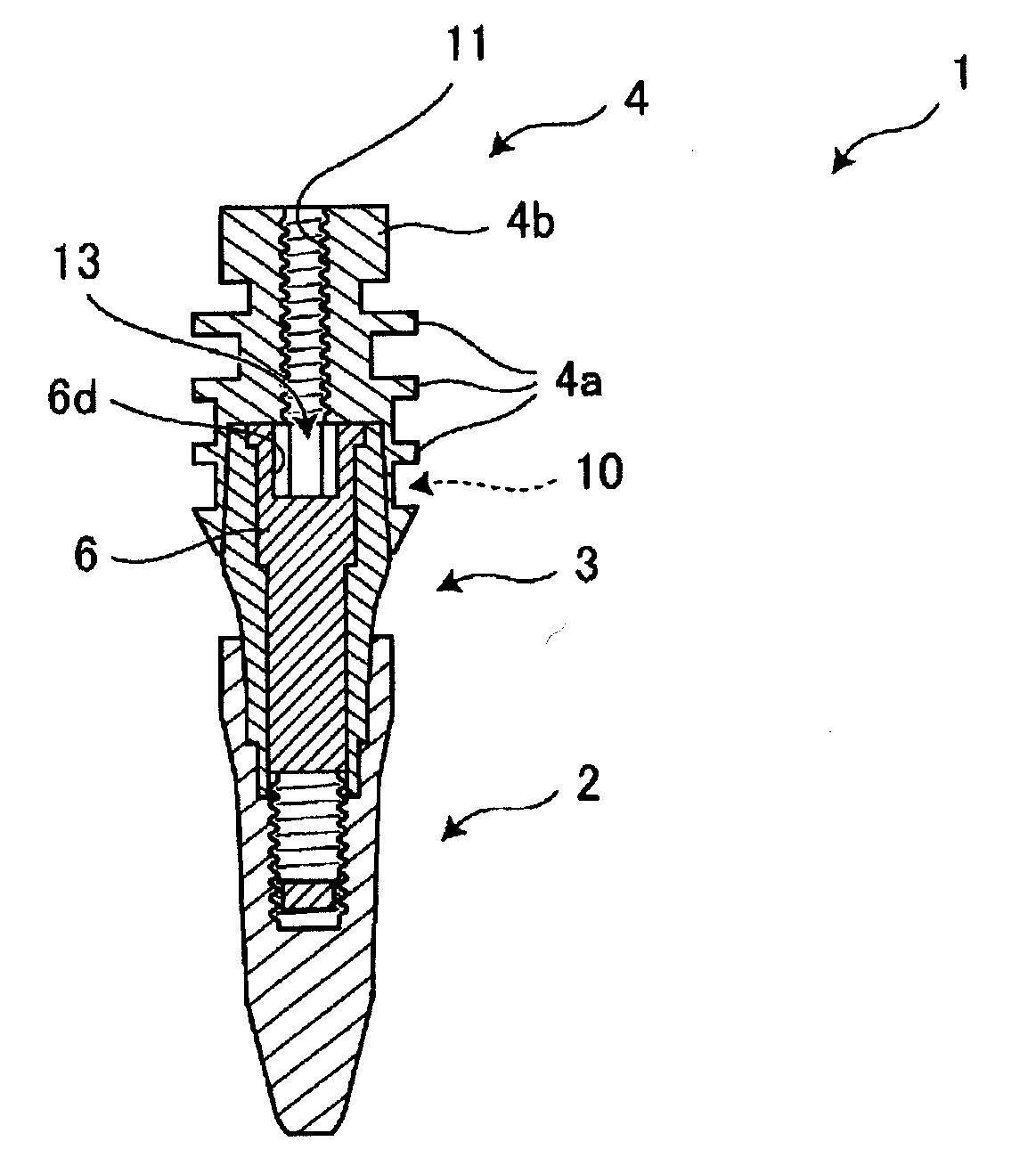
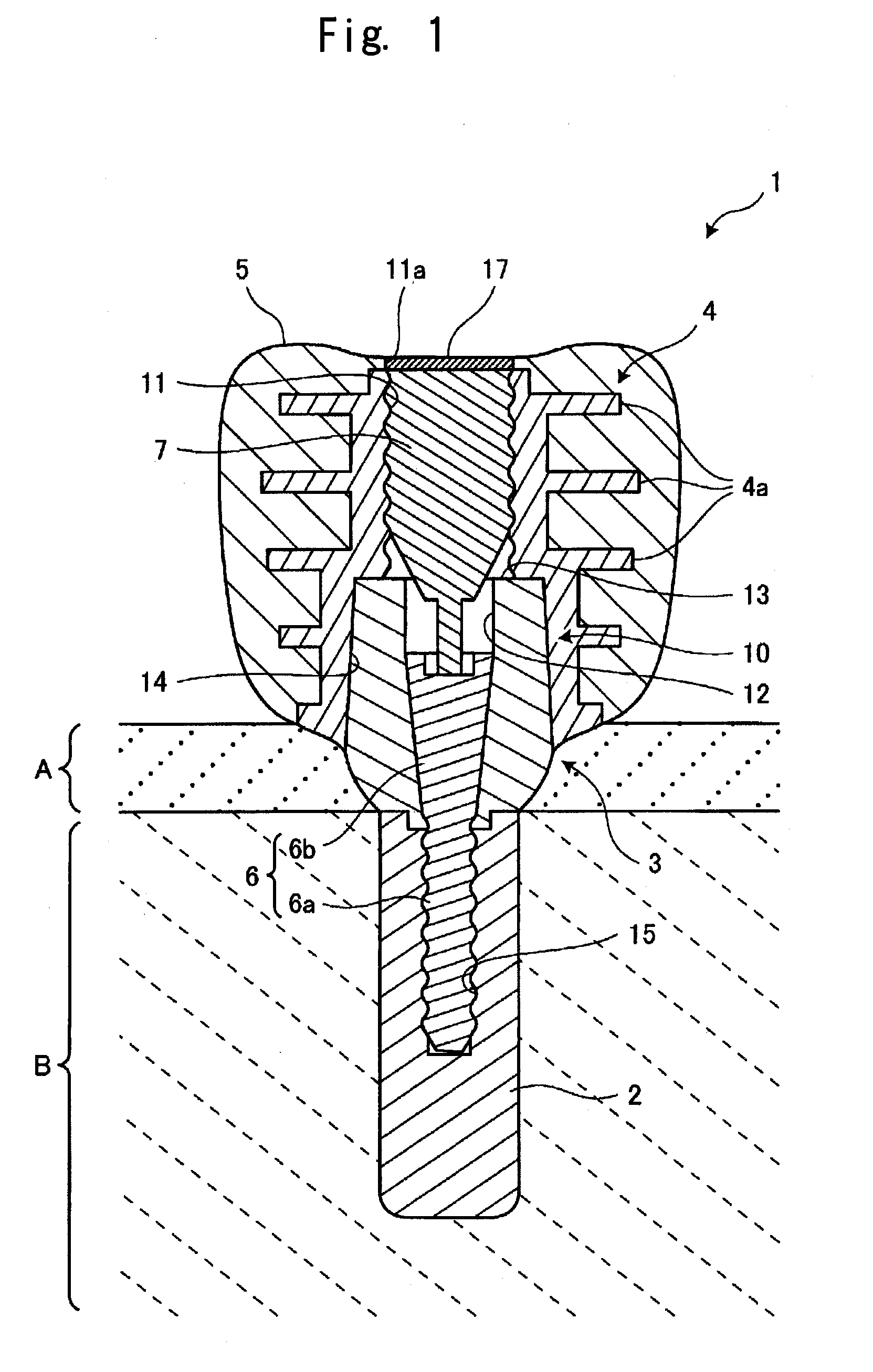
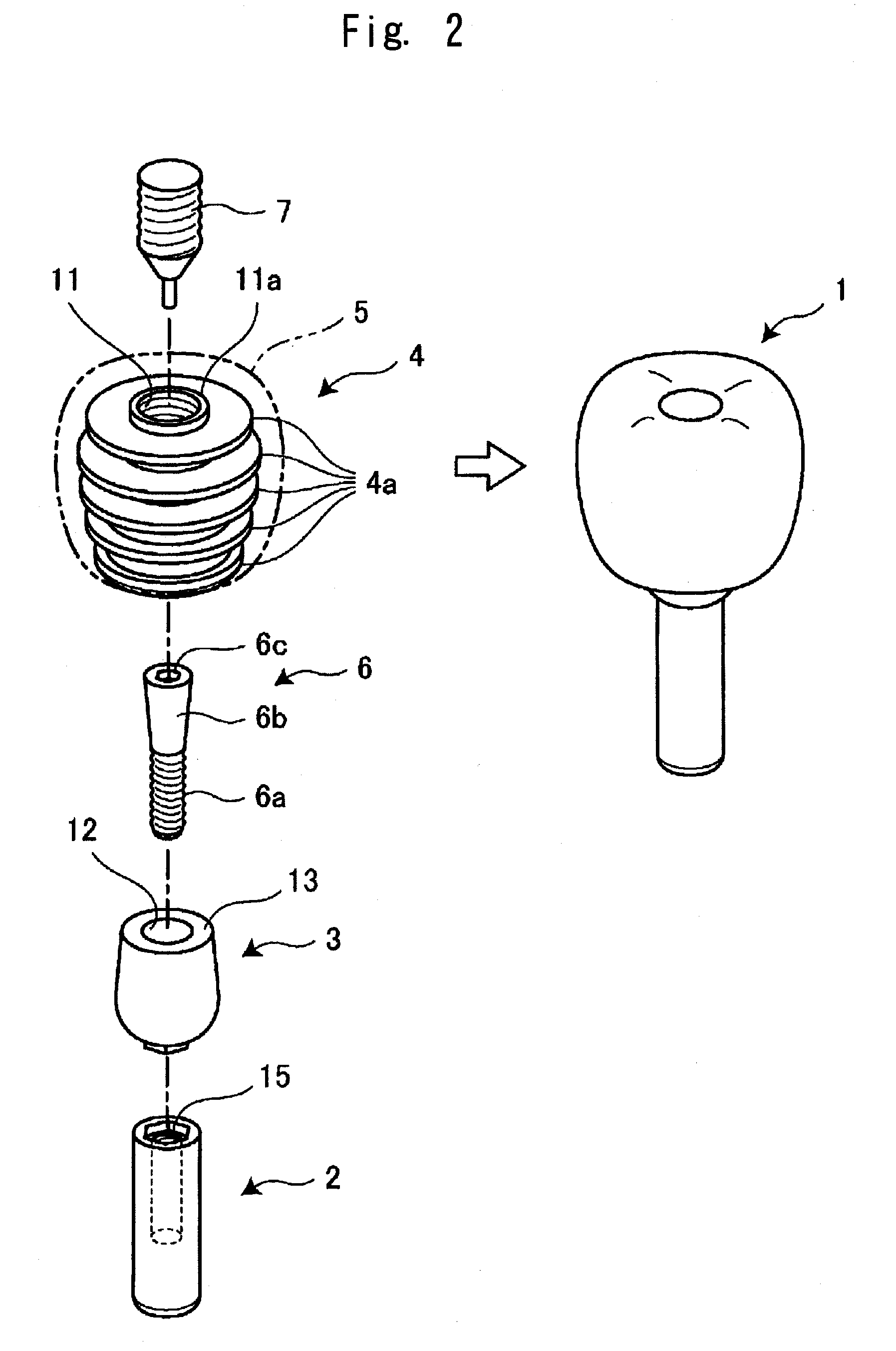
[0112]As shown in FIG. 1 and FIG. 2, the dental implant structure 1 of this embodiment is constituted of a fixture 2 which is embedded into a jaw bone B, an abutment 3 which is placed on and fixed to an upper portion of the fixture 2, an artificial tooth base 4 which is placed on and fixed to an upper portion of the abutment 3, and an artificial tooth 5 which is mounted on the artificial tooth base 4.

[0113]In addition, an outer peripheral surface of the abutment 3 and an inner peripheral surface of a fitting hole 14 formed in the artificial tooth base 4 are respectively formed into tapered surfaces which co...


PUM


Abstract

A human body implant structure includes: a support anchor which is embedded into a bone body; a support base which is placed on and fixed to an upper portion of the support anchor; and a lost-part compensation part which is mounted on an upper portion of the support base, wherein the support anchor and the support base are configured to be detachably fitted to each other by way of the taper fitting structure where the support anchor and the support base are brought into close contact with each other, and a stepped portion which is formed of an upper surface of the support anchor is formed on a boundary between a female threaded hole which is vertically formed in the support base and a vertical hole formed in the upper surface of the support anchor.

Description

CROSS-REFERENCE TO RELATED APPLICATIONS[0001]This application is based on and claims the benefit of priority from Japanese Patent Application No. 2009-203110 filed on Sep. 2, 2009 and Japanese Patent Application No. 2010-104971 filed on Apr. 30, 2010, the entire contents of which are incorporated herein by reference.BACKGROUND[0002]1. Field[0003]The present invention relates to the human body implant structure such as a dental implant, a method of assembling the human body implant structure, and a method of disassembling the human body implant structure for disassembling the implant structure which is once assembled for repair and inspection.[0004]2. Description of the Related Art[0005]To consider a case where a part of a human body is lost due to an accident, a disease or the like, there has been known a technique which compensates for such a lost part with a lost-part compensation part such as an artificial tooth, an artificial eye or an artificial ear, for example.[0006]In such a...

Claims


Application Information

Patent Timeline
Patent Type & Authority Applications(United States)
IPC IPC(8): A61C8/00A61C9/00A61F2/14A61F2/18
CPCA61C8/005A61C7/36A61C8/0001A61C8/006A61C8/0068A61C8/0089A61C8/0096A61C8/0098A61F2/14A61F2/18
Inventor SHIMODA, TSUNEHISA
Owner ARTHRO
Why Eureka
Try Eureka