Ultrasonic diagnostic apparatus

a diagnostic apparatus and ultrasonic technology, applied in the field of ultrasonic diagnostic apparatus, can solve the problems of reducing the correlation coefficient, unable to obtain the elastic image on which the elasticity of biological tissue has been reflected accurately, and the correlation coefficient at the correlation arithmetic operation becomes low, so as to achieve the effect of stable calculation results

Active Publication Date: 2011-03-03
GE MEDICAL SYST GLOBAL TECH CO LLC
View PDF15 Cites 26 Cited by
  • Summary
  • Abstract
  • Description
  • Claims
  • Application Information

AI Technical Summary

Benefits of technology

[0026]Results of calculations obtained every frame by the correlation coefficient average unit are averaged over a plurality of frames and displayed on the display unit, thereby making it possible to display a stable result of calculation.
[0027]In yet another embodiment, the value calculated by the ratio calculator using the average value of physical quantities obtained with respect to correlation windows in which a correlation arithmetic operation on correlation coefficients each greater than or equal to a predetermined threshold value has been p...

Problems solved by technology

Each echo signal acquired in such a case contains noise due to the lateral shift, so that there is a fear that a correlation coefficient at a correlation arithmetic operation becomes low.
There is a fear that when the degrees of the pressure and its relaxation are excessive, deformation of the biological tissue is so excessive that the correlation windows set to the two echo signals are not matched with each other, thus reducing the correlation coefficient.
Thus, as the correlation coefficient at the correlation arithmetic operation becomes lower, the elastic image on which the elasticity of the biological tissue has been reflected accurately cannot be obtained.
The intensity of each echo signal becomes insufficient in a region small in the number of ultrasound reflectors and at a deep portion of a biological tissue, to which transmit ultrasound is hard to achieve due to its attenuation.
Thus, a correlation coefficient at a correlation arithmetic operation on each echo signal insufficient in signal intensity becomes low.
Accordingly, an elastic image o...

Method used


Image

  • Ultrasonic diagnostic apparatus
  • Ultrasonic diagnostic apparatus
  • Ultrasonic diagnostic apparatus

Examples


first embodiment

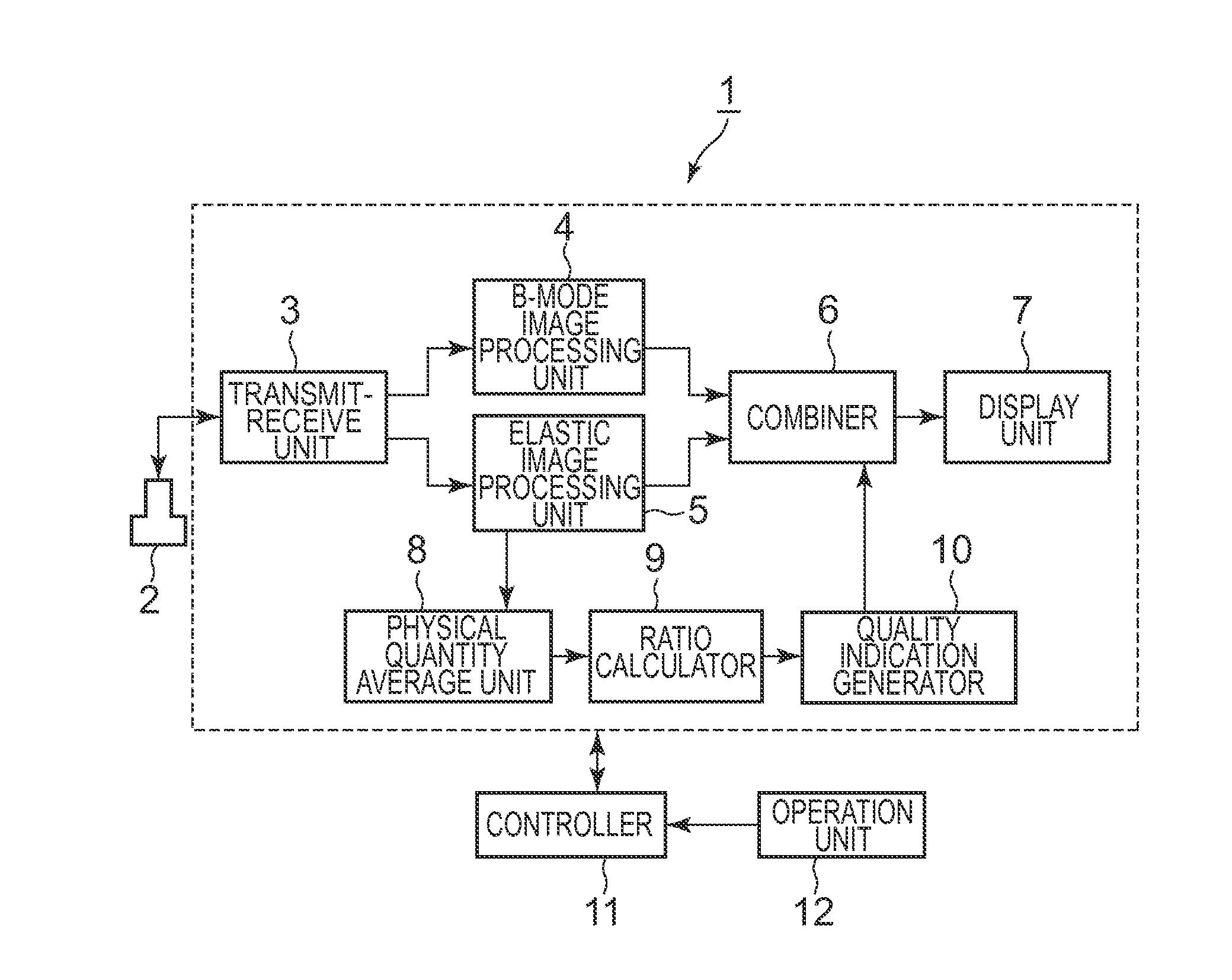
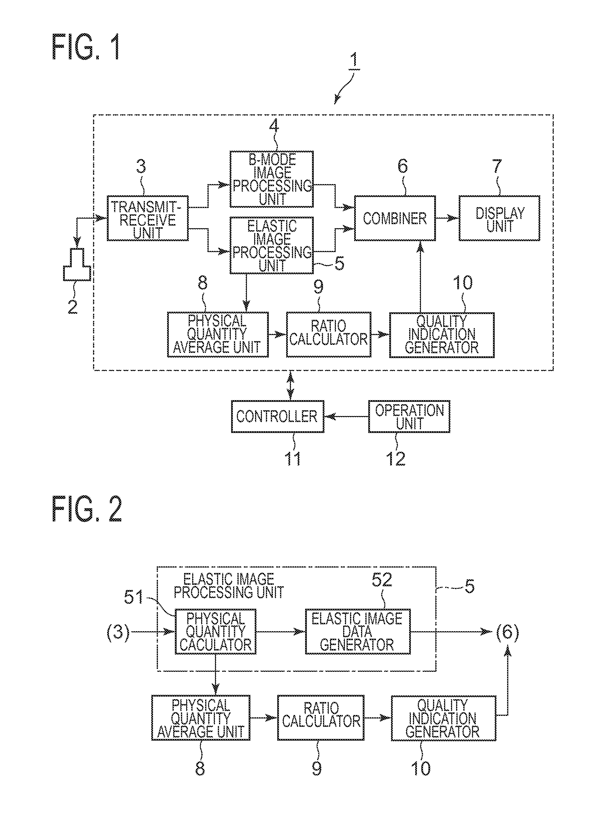
[0050]A first embodiment will first be explained based on FIGS. 1 through 10. An ultrasonic diagnostic apparatus 1 shown in FIG. 1 is equipped with an ultrasonic probe 2, a transmit-receive unit 3, a B-mode image processing unit 4, an elastic image processing unit 5, a combiner 6, a display unit 7, a physical quantity average unit 8, a ratio calculator 9 and a quality indication generator 10. Further, the ultrasonic diagnostic apparatus 1 includes a controller 11 and an operation unit 12.

[0051]The ultrasonic probe 2 transmits ultrasound to a biological tissue and receives its echoes. An elastic image is generated as described later based on echo signals acquired by performing the transmission / reception of the ultrasound while repeating pressure and relaxation in a state in which the ultrasonic probe 2 is being brought into contact with the surface of the biological tissue.

[0052]The transmit-receive unit 3 drives the ultrasonic probe 2 under a predetermined scan condition to perfor...

second embodiment

[0090]A second embodiment will next be explained based on FIGS. 11 and 12. Incidentally, the same reference numerals are respectively attached to the same components as those in the first embodiment, and their explanations will therefore be omitted.

[0091]An ultrasonic diagnostic apparatus 20 according to the present embodiment is not equipped with the physical quantity average unit 8 and the ratio calculator 9, but equipped with a correlation coefficient average unit 21 instead of them. The correlation coefficient average unit 21 is one example illustrative of an embodiment of the correlation average unit 21 in the invention.

[0092]The operation of the ultrasonic diagnostic apparatus 20 according to the present embodiment will be explained. The present embodiment is different from the first embodiment in the method for generating the quality indication QG. Described concretely, the correlation coefficient average unit 21 calculates, for every frame, average values CAV in regions of i...

third embodiment

[0096]A third embodiment will next be explained based on FIGS. 13 and 14. Incidentally, the same reference numerals are respectively attached to the same components as those in the first and second embodiment, and their explanations will therefore be omitted.

[0097]An ultrasonic diagnostic apparatus 30 of the present embodiment is equipped with the physical quantity average unit 8, ratio calculator 9, quality indication generator 10, correlation coefficient average unit 21 and the like. Further, the ultrasonic diagnostic apparatus 30 further includes a multiplier 31. The multiplier 31 is one example illustrative of an embodiment of a multiplier in the invention.

[0098]The generation of the quality indication QG at the ultrasonic diagnostic apparatus 30 of the present embodiment will be explained. The physical quantity average unit 8 selects correlation windows wherein a correlation arithmetic operation in which a correlation coefficient C is greater than or equal to a predetermined th...


PUM


Abstract

An ultrasonic diagnostic apparatus includes a physical quantity calculator for setting correlation windows to two echo signals obtained by transmission/reception of ultrasound to and from a biological tissue and different in time on the same sound rays and performing a correlation arithmetic operation between the correlation windows to thereby calculate physical quantities related to elasticity of respective regions in the biological tissue, an elastic image data generator for generating elastic image data of the biological tissue with respect to an elastic image forming region of a transmission/reception surface of the ultrasound, based on the physical quantities, a physical quantity average unit for calculating an average of the physical quantities in the elastic image forming region for every frame, a comparator for comparing a value calculated by the physical quantity average unit and a preset average value of the physical quantities, and a notification unit for notifying a result of comparison by the comparator.

Description

CROSS REFERENCE TO RELATED APPLICATIONS[0001]This application claims the benefit of Japanese Patent Application No. 2009-195004 filed Aug. 26, 2009, which is hereby incorporated by reference in its entirety.BACKGROUND OF THE INVENTION[0002]The present invention relates to an ultrasonic diagnostic apparatus, and particularly to an ultrasonic diagnostic apparatus that displays an elastic image indicative of the hardness or softness of a biological tissue.[0003]An ultrasonic diagnostic apparatus, which combines a normal B-mode image and an elastic image indicative of the hardness or softness of a biological tissue together and displays the result of combination, has been disclosed in, for example, Japanese Unexamined Patent Publication No. 2005-118152 or the like. In this type of ultrasonic diagnostic apparatus, the elastic image is generated in the following manner. First, ultrasound is transmitted and received to and from the biological tissue while repeating pressure from a body sur...

Claims


Application Information

Patent Timeline
IPC IPC(8): A61B8/14
CPCA61B8/08A61B8/14A61B8/463G01S7/52073G01S7/52036G01S7/52042G01S7/5205A61B8/485
Inventor TANIGAWA, SHUNICHIROMIYAMA, KOJIFUNAYA, SEIJI
Owner GE MEDICAL SYST GLOBAL TECH CO LLC
Why Eureka
Try Eureka