Method for compensating for angular transmission error of wave gear device

a wave gear and transmission error technology, applied in the direction of non-deflectable wheel steering, program control, underwater vessels, etc., can solve the problems of inability to compensate for these synchronous components in a semi-closed loop control system, difficult to inhibit positioning errors at times, and inability to measure the absolute angle of the load shaft, so as to reduce the synchronous component of the motor shaft positioning precision. , to achieve the effect of preventing or inhibiting the effect of positioning precision

Active Publication Date: 2011-03-03
HARMONIC DRIVE SYST IND CO LTD +1
View PDF3 Cites 27 Cited by
  • Summary
  • Abstract
  • Description
  • Claims
  • Application Information

AI Technical Summary

Benefits of technology

[0019]The motor shaft synchronous component included in the angular transmission error of a wave gear device is an angular transmission error component that is created by a cumulative pitch error of the flexspline and the circular spline. In the compensation method according to the present invention, the motor shaft synchronous component is considered to be an oscillation source, and the effect of the motor shaft synchronous component on the load position is canceled out by the compensation current command, resulting in a state in which there is no action of the motor shaft synchronous component. As a result, the reduction of the positioning precision by the motor shaft synchronous component can be inhibited or prevented, and compensation can be provided for the oscillation component brought about by the dynamic motor shaft synchronous component during the positioning response.

Problems solved by technology

Among these, the F / S-W / G relative rotation-synchronous component has no reproducibility in measured results, and the load shaft synchronous component has amplitude that varies with the assembled state of the load, and there are no means available to measure the absolute angle of the load shaft.
It is therefore impossible to compensate for these synchronous components in a semi-closed loop control system.
With the conventional compensation methods, however, it is difficult to inhibit positioning errors at times other than during a no-load operation.

Method used


Image

  • Method for compensating for angular transmission error of wave gear device
  • Method for compensating for angular transmission error of wave gear device
  • Method for compensating for angular transmission error of wave gear device

Examples


Embodiment Construction

Configuration of Positioning System

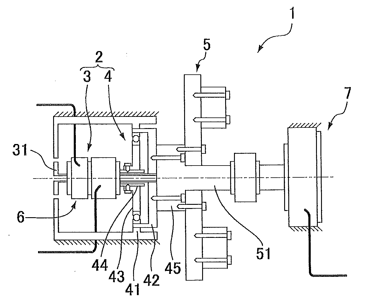
[0030]FIG. 1 is a schematic view of a positioning system (experimental device) that includes an actuator provided with a wave gear device and used in the present embodiment, and Table 1 shows the specifications. An actuator 2 incorporated into a positioning system 1 has a motor 3 and a wave gear device 4, and a load device 5 is connected to the wave gear device 4. A motor shaft encoder 6 is attached to the back end of a motor shaft 31 fixed coaxially to a rotor (not shown) of the motor 3. The motor position (rotational position of the motor shaft 31) is detected by the motor shaft encoder 6. The wave gear device 4 has a circular spline (C / S) 41, a flexspline (F / S) 42, and a wave generator (W / G) 43. An input shaft 44 of the wave gear device is linkably fixed in a coaxial manner to the wave generator 43, and the input shaft 44 of the wave gear device is also fixedly connected in a coaxial manner to the motor shaft 31. An output shaft 45 of the wave g...


PUM


Abstract

A positioning system (1) provided with an actuator (2) having a wave gear device (4) is driven and controlled by a semi-closed loop control for controlling the load position of a load device (5) based on the motor position of a motor shaft (31) of a motor (3). In a method for compensating for an angular transmission error by compensating for a motor shaft synchronous component θSync that occurs in synchrony with the motor position and is a relative rotation-synchronous component that includes an angular transmission error component of the wave gear device (4), the positioning system (1) is represented as a two-inertia model, and the motor shaft synchronous component θSync is represented as an oscillation source for producing a twisting action between the two inertia bodies in the two-inertia model. A motor current command iref is corrected by a compensation current command icomp calculated so as to allow the effect of the motor shaft synchronous component θSync on the load position to be compensated in this case, and a motor position command r is corrected by a motor position correction signal θcomp calculated in order to compensate for the effect of the motor shaft synchronous component θSync.

Description

TECHNICAL FIELD[0001]The present invention relates to a method for compensating for an angular transmission error of a wave gear device in cases in which driving and controlling an actuator constructed so as to reduce the speed of output rotation of a motor via the wave gear device and to transmit the output rotation to a load device are performed by a semi-closed loop control for controlling the position of the load shaft of the load device on the basis of the detected position of the motor shaft.[0002]More specifically, the present invention relates to a method for compensating for an angular transmission error in order to inhibit or prevent oscillations brought about by a motor shaft synchronous component occurring in synchrony with the motor position (rotational position of the motor shaft) as an angular transmission error component (relative rotation-synchronous component) that occurs in synchrony with the relative rotation of each constituent element of the wave gear device. T...

Claims


Application Information

Patent Timeline
Patent Type & Authority Applications(United States)
IPC IPC(8): G06F19/00F16H1/32G05D3/12H02P29/00
CPCF16H49/001G05B19/404G05B2219/41117H02P23/14G05B2219/42155G05B2219/49292G05B2219/41143
Inventor SASAKI, KOZOOKITSU, YOSHIFUMIYAJIMA, TOSHIOIWASAKI, MAKOTO
Owner HARMONIC DRIVE SYST IND CO LTD
Why Eureka
Try Eureka