Method for operating a gas turbine plant

a gas turbine and plant technology, applied in the direction of gas turbine plants, non-combustible gases/liquids supply, combustion process, etc., can solve the problems of less stable flame, large non-combustible product generation, and low no/sub>x/sub>generation, so as to improve the power output without impairing the reliance of the gas turbine, reduce the flame temperature, and reduce the amount of non-combustible products

a gas turbine and plant technology, applied in the direction of gas turbine plants, non-combustible gases/liquids supply, combustion process, etc., can solve the problems of less stable flame, large non-combustible product generation, and low no/sub>x/sub>generation, so as to improve the power output without impairing the reliance of the gas turbine, reduce the flame temperature, and reduce the amount of non-combustible products

US20110056211A1Active Publication Date: 2011-03-10ANSALDO ENERGIA SWITZERLAND AG

Image

  • Method for operating a gas turbine plant
  • Method for operating a gas turbine plant
  • Method for operating a gas turbine plant

Examples


Embodiment Construction

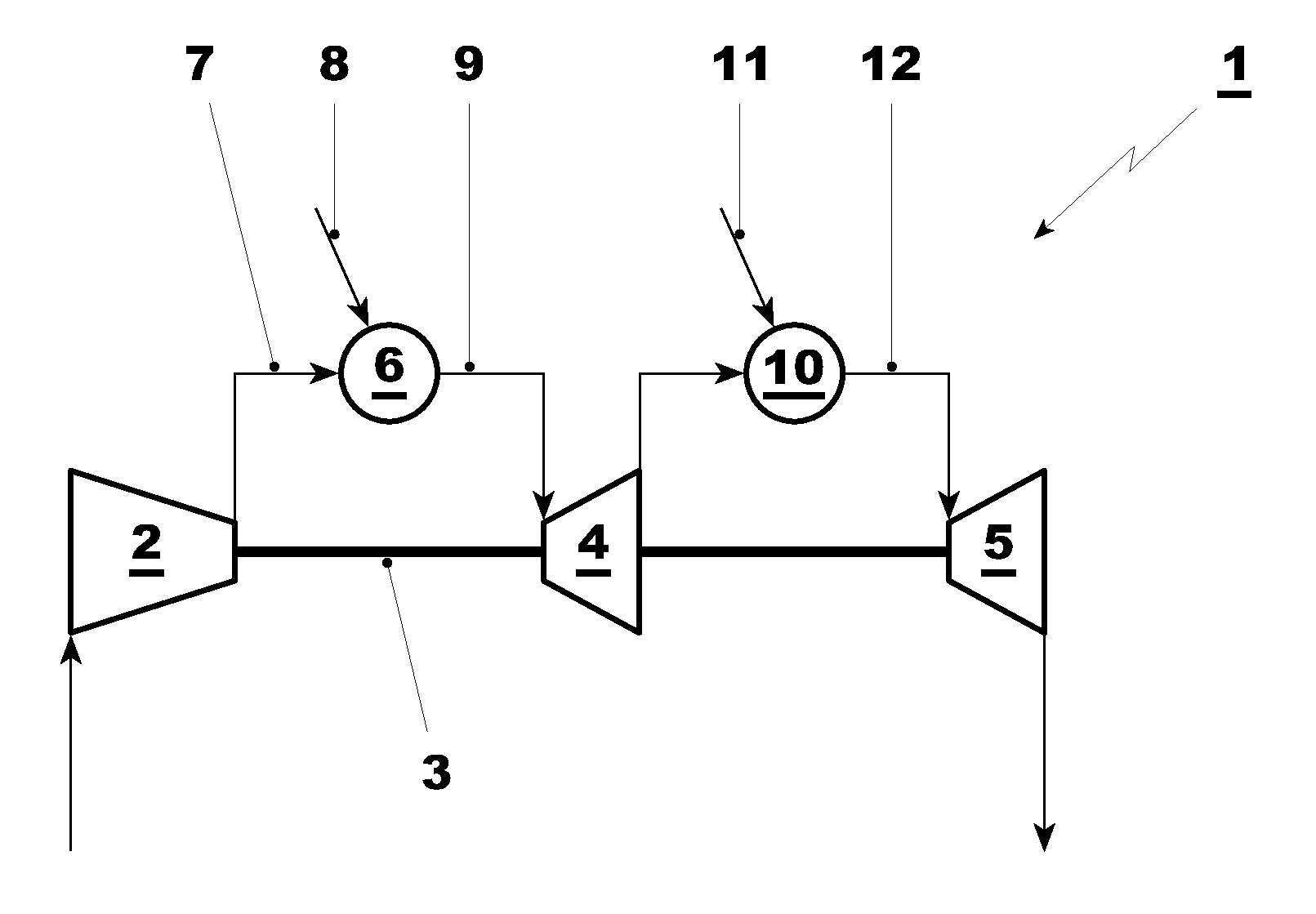
[0025]Methods embodying principles of the present invention can be implemented using a gas turbine plant having two (or more) combustion chambers, wherein a second combustion chamber is fed with the hot gases generated in a first combustion chamber.

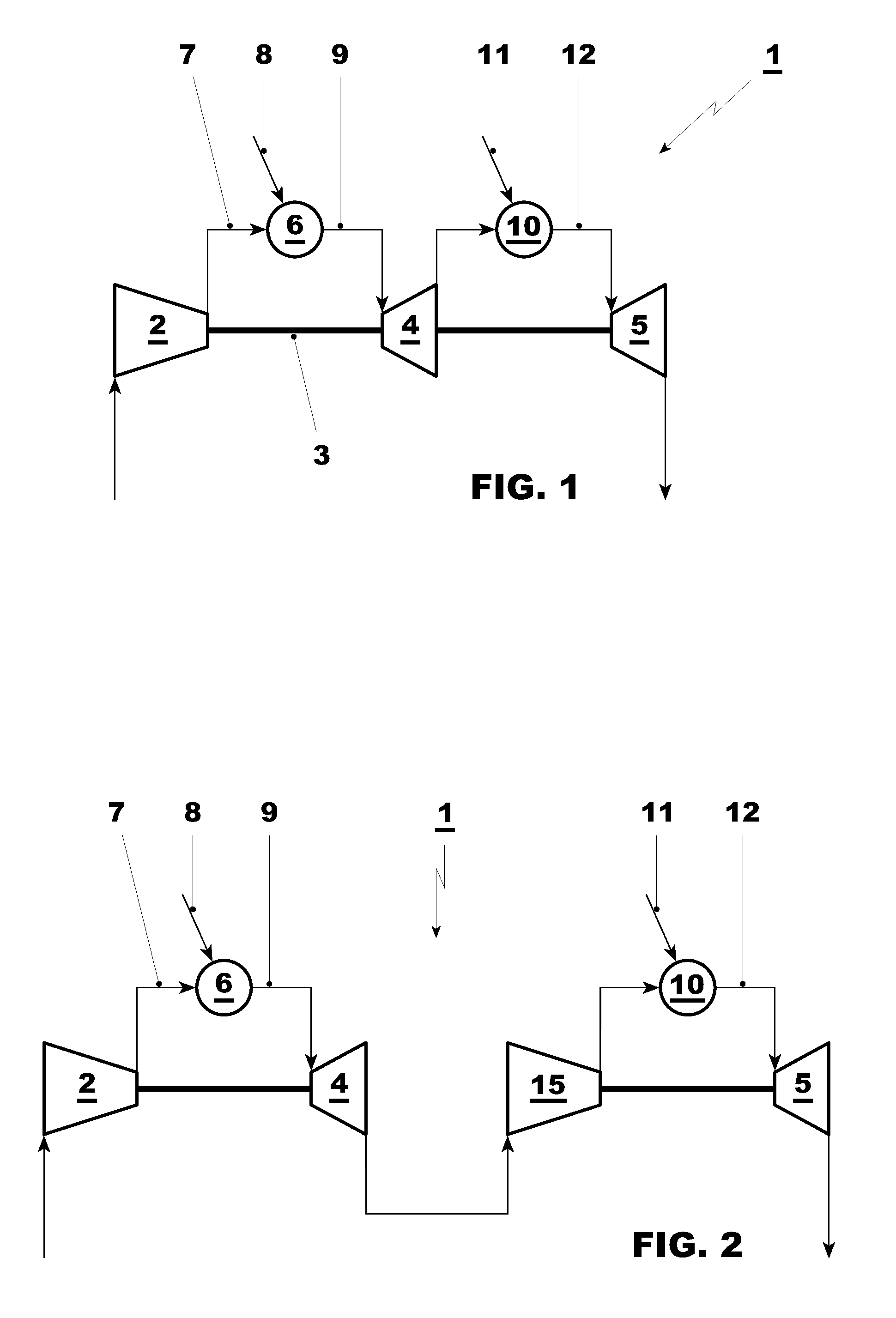
[0026]In this respect, FIGS. 1 and 2 show two different embodiments of gas turbine plants that are able to implement methods embodying principles of the present invention.

[0027]It is anyhow clear that also different gas turbine plants may implement methods as described herein, provided that they have two combustion chambers with the second combustion chamber that is fed with the hot gases generated in the first combustion chamber.

[0028]The gas turbine plant 1 of FIG. 1 has a compressor 2 connected via a shaft 3 to a high pressure turbine 4 and low pressure turbine 5.

[0029]In addition, a first combustion chamber 6 is provided that is fed with compressed air 7 from the compressor 2; in the combustion chamber 6, a first fuel 8 is injected an...


PUM


Abstract

A gas turbine plant has a compressor (2), a first combustion chamber (6) followed by a high pressure turbine (4), a second combustion chamber (10) and a low pressure turbine (5). In the first combustion chamber (6) a first gaseous fuel (8) is injected and combusted, generating first hot gases (9) that are at least partly expanded in the high pressure turbine (4), and in the second combustion chamber (10) a second fuel (11) is injected in the at least partly expanded hot gases generated in the first combustion chamber (6) and combusted, generating second hot gases (12) that are expanded in the low pressure turbine (5). In the first combustion chamber (6) water is also injected to increase the gas turbine plant power output. In the first combustion chamber (6) a water flow rate is injected compatible with a predetermined flame stability limit. In the second combustion chamber (6) the flame temperature is regulated to burn the non-combusted products generated in the first combustion chamber (6) to bring their amount below a predetermined emission limit, without exceeding a predetermined NOx emission limit.

Description

[0001]This application claims priority under 35 U.S.C. ยง119 to European application no. 09168896.0, filed 28 Aug. 2009, the entirety of which is incorporated by reference herein.BACKGROUND[0002]1. Field of the Invention[0003]The present invention relates to methods for operating a gas turbine plant.[0004]In particular a gas turbine plant useful for implementing a method in accordance with principles of the present invention has a first and a second combustion chambers, such that hot gases are generated in the first combustion chamber and are expanded in a high pressure turbine; then these hot gases generated in the first combustion chamber are introduced into a second combustion chamber wherein further fuel is injected and combusted to generate second hot gases to be further expanded in a low pressure turbine.[0005]In this respect, the gas turbine plant may include one (or more) sequential combustion gas turbine units, i.e., gas turbines having a compressor, a first combustion chamb...

Claims


Application Information

Patent Timeline
10 Mar 2011
Publication
US20110056211A1
IPC
F02C3/30
CPC
F02C3/305; F23R2900/03341; F23L7/002; F02C6/003
Inventors
SCHELL, SUSANNE; MEEUWISSEN, THIEMO